
Publication archive
Quality inspection of rotary instruments
Insight into a published application or lecture from the CRETEC archive.
Archive content: Information refers to the original publication status. Please coordinate current execution, scope of services and availability with CRETEC.
 Enlarge the image ↗
 Enlarge the image ↗
 Enlarge the image ↗
 Enlarge the image ↗
 Enlarge the image ↗
 Enlarge the image ↗
 Enlarge the image ↗
 Enlarge the image ↗
 Enlarge the image ↗
 Enlarge the image ↗
Quality inspection of rotary instruments
Project type:
QBICs
Date
2019
As part of the project at the customer, rotating instruments are to be optically tested in an automation unit. Industrial machine vision makes it possible to integrate a control between successive process steps despite high cycle rates and frequently unfavorable framework conditions, such as poor accessibility. This means that not only better data about the process can be obtained, but also bad parts can be separated out. The manufactured products must be monitored reliably, objectively, as fully automated as possible and in relation to defined product and quality specifications.
The present specification/obligation specification describes the required properties of the optical inspection system. The specifications were created with the aim of ensuring the optical testing of rotating instruments in impeccable quality and high process availability.
1.1. Tasks
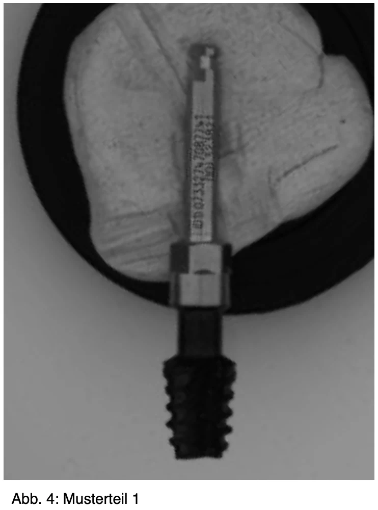
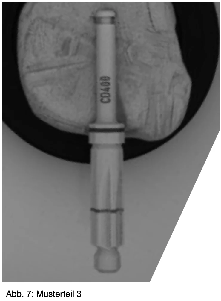
Rotating instruments are to be automatically checked optically in the area of CM (custom made). The following components shall be tested:
• Laser inscription (missing, incomplete, wrong, wrong position)
• UDI marking (missing, incomplete, wrong, wrong position)
• Laser marking (missing, incomplete, wrong position)
• Color ring (missing, wrong color, incomplete, overcoloured)
The object is to be classified in the field of surface testing. The inspection system should read code and characters on rotating instruments, detect defects in the areas of the components being tested, and check the components for completeness and position. Faulty instruments should be identified and separated as n.i.O. As part of the project, it will be checked whether a inspection system can be integrated into an automation unit that is still to be developed. The test time/instrument should take into account the cycle time of 10 seconds. It would be better to reduce the cycle time as far as possible.
1.1.1. Previous approach
• Manual visual inspection by experts with 10xLupe, 2xRinglupe
• Classification i.O./n.i.O. according to Quality Book
• Test time: 1000/1000 min, 1000/400 min
• Annual production of rotating instruments: approx. 800,000 pieces
Optical testing of the UDI marking is particularly challenging for employees, as it is a 12-14 digit number combination that is matched on each instrument. Due to the reflections, the font size and the length of the marking, testing is time-consuming and difficult.
1.1.2. Validation
In order to qualify the inspection system, the following values shall be known:
• Detection rate
• Classification rate
• False alarm rate (pseudo committee) •Repeatability
• Long-term stability
• Others?
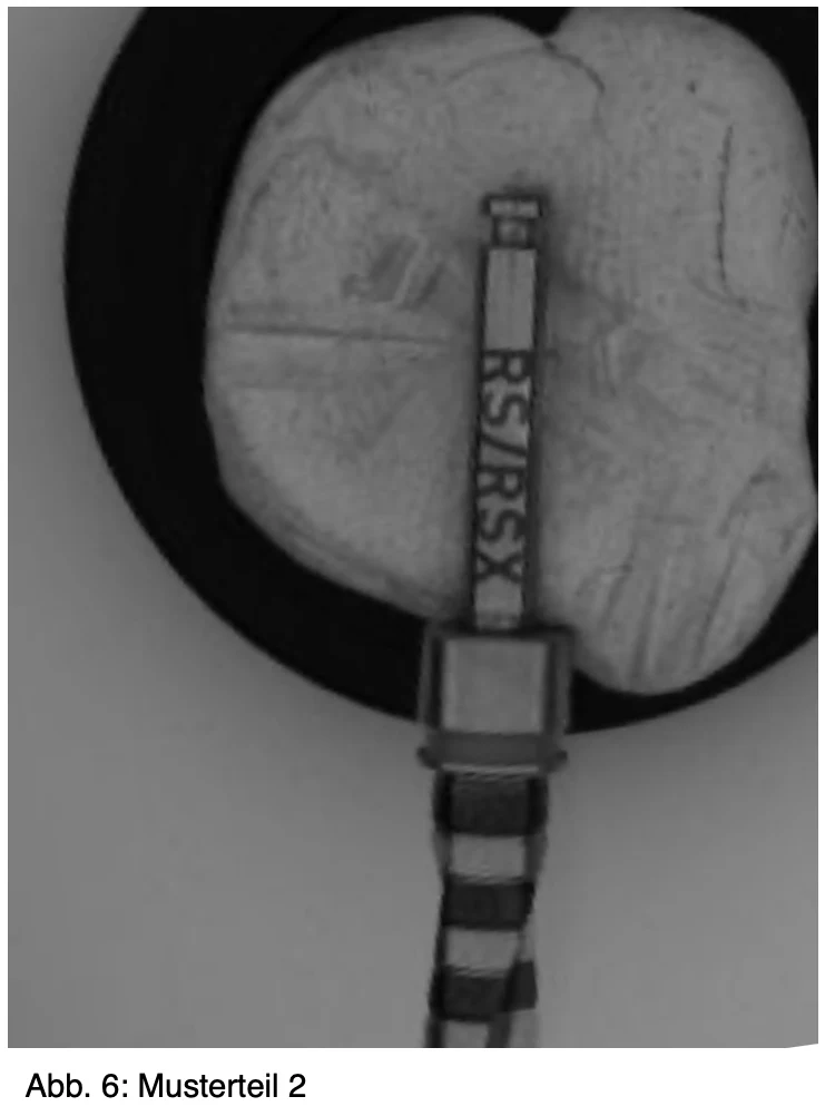
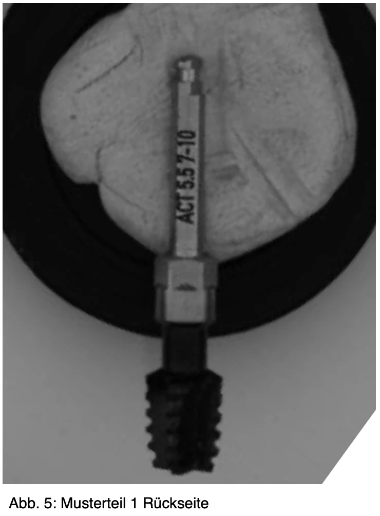
In order to validate the system, sample parts, sample catalogues and parts with reference statements/limiting patterns are provided. The sample parts shall be used to produce a proof of ability with appropriate documentation. Methods for validation are typically used in pre-, final inspection and test equipment monitoring. In this case, VDI/VDE/VDMA 2632 should be used.
Statistical evaluations (mean values, variances) of the inspection results as well as the warning/intervention limits should be possible. The data should be provided by the inspection system for further processing.
1.1.3. Time requirements
• Required speed/clock time: 10sec/instrument
• Throughput: approx. 800,000 instruments/year
1.1.4. Required availability
The optical inspection system should receive the expected result from the labeling machine. What solutions are available if the database is faulty or non-existent? A verification is then carried out. In addition, the optical inspection system should create a database for itself upon successful verification in order to detect incorrect entries from the operator on the labeling machine. An important question is the teaching of new products. How long does that take? How expensive is that?
• Maximum planned/unplanned downtimes
Mean Time Between Failures (MTBF)
Mean Time to Repair (MRTTR)
Mean Time Between Maintenance (MTBM)
1.2. Test object
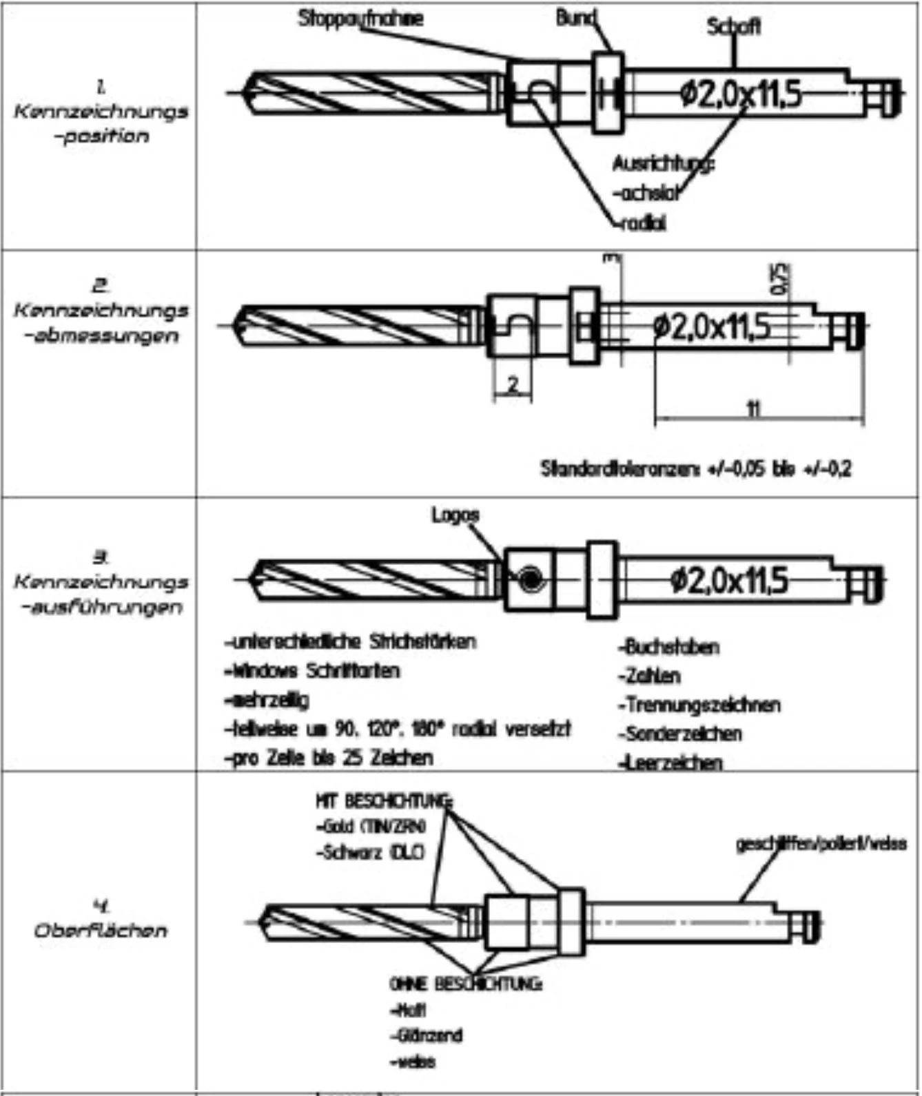
The objects to be tested are rotating instruments from the Custom Made area. The following table shows the detailed requirements. The optical system should check the marking position. It should recognize the location and position of the signs. In addition, the system should determine the marking dimensions and compare them with those required. In addition, the system should recognise and check for completeness the different types of labelling. The optical system shall be capable of carrying out the tests on different surfaces. In this case, gloss and reflections can make image acquisition more difficult. Furthermore, the depth markings in the region of the working part are to be checked with respect to position and completeness. In addition, the color ring is to be tested. The color ring is located exclusively on cylindrical surfaces. The colour, design and position should be checked.
The data are given in the unit mm.
2 Growing situation
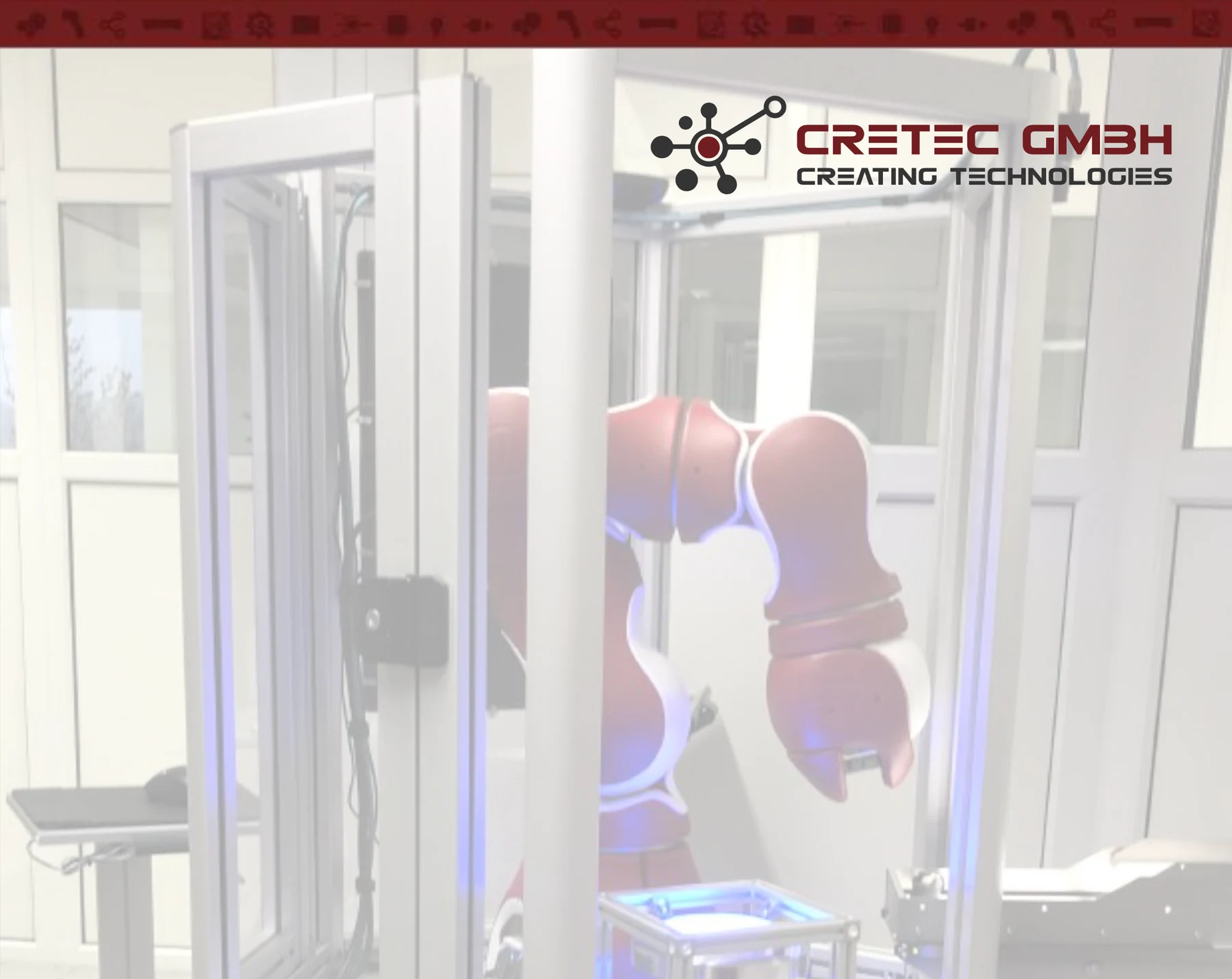
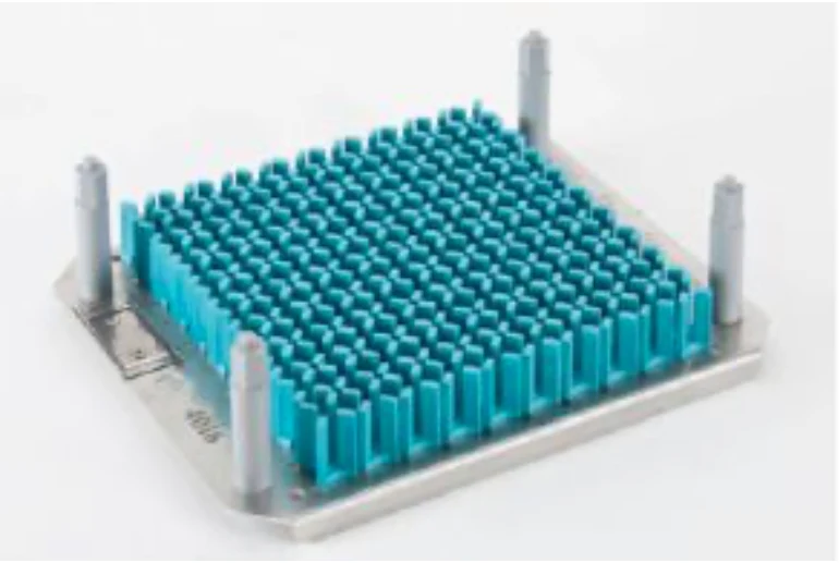
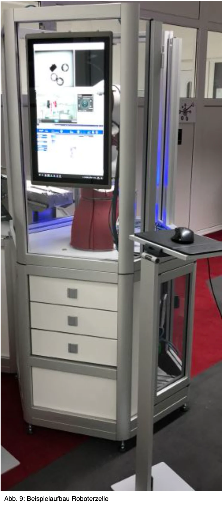
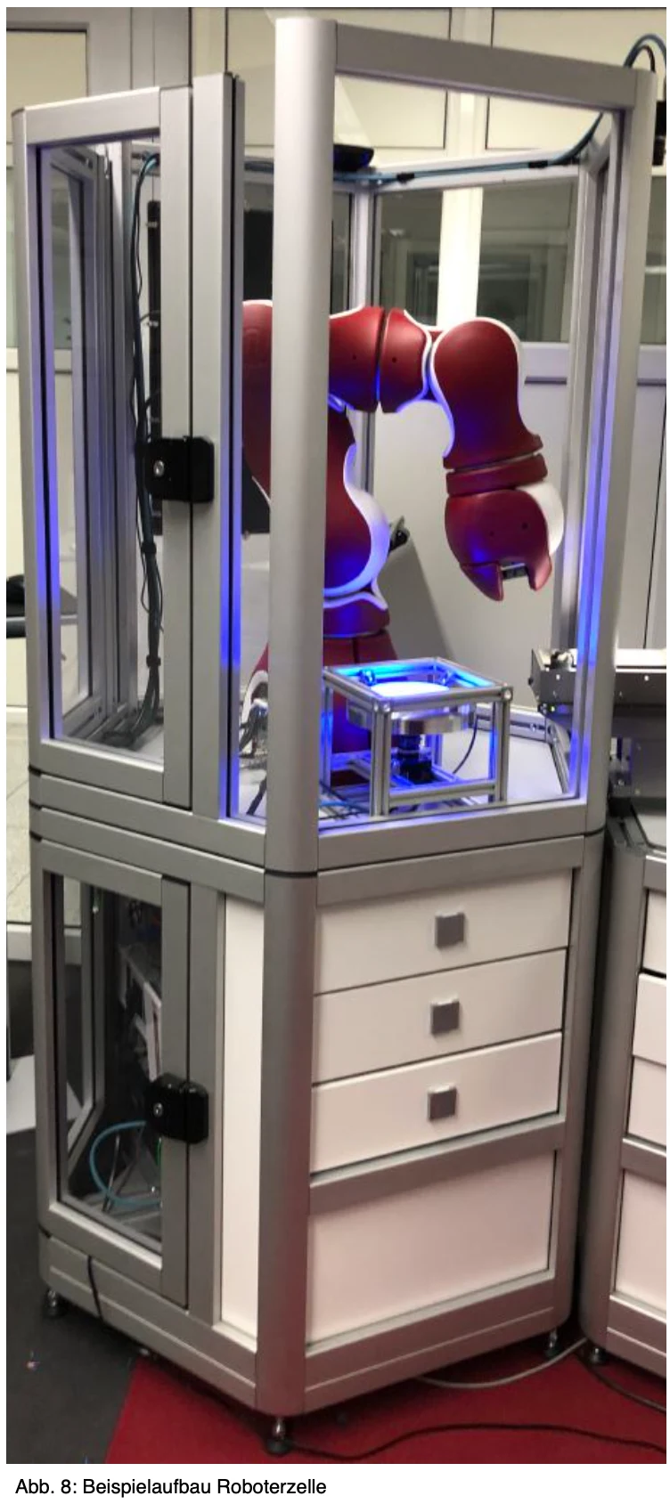
The test incl. MRK robot can be performed in a standard CRETEC inspection cell (QBIC). The customer provides the goods carriers and parts under inspection and CRETEC integrates them into the existing standard system.
The robot removes the part under inspection from the tray, tests as described by means of image processing, and subsequently sets the test object in an i.O. or n.i.O. Tray off.
The inspection cell is movable by means of integrated extendable rollers.
The dimensions of the inspection cell are shown in the drawing ‘Inspection cell’:
The protective screens can be removed from the profiles in order to be able to connect a separate robot cell as planned.
Request for this application →