Publication archive
Inspection cell for heat-sink surface quality
Insight into a published application or lecture from the CRETEC archive.
Archive content: Information refers to the original publication status. Please coordinate current execution, scope of services and availability with CRETEC.
 Enlarge the image ↗
 Enlarge the image ↗
 Enlarge the image ↗
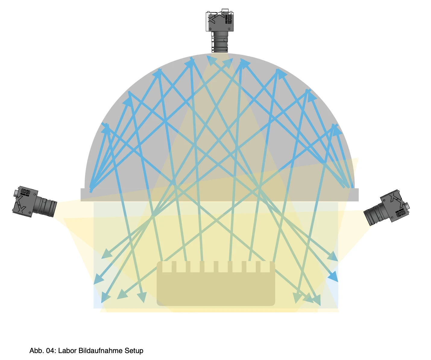 Enlarge the image ↗
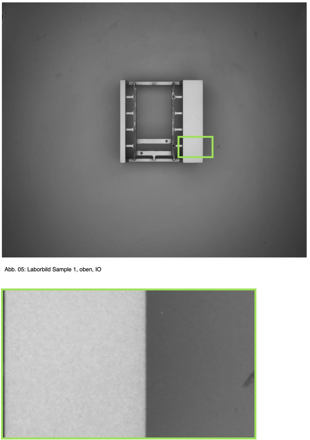 Enlarge the image ↗
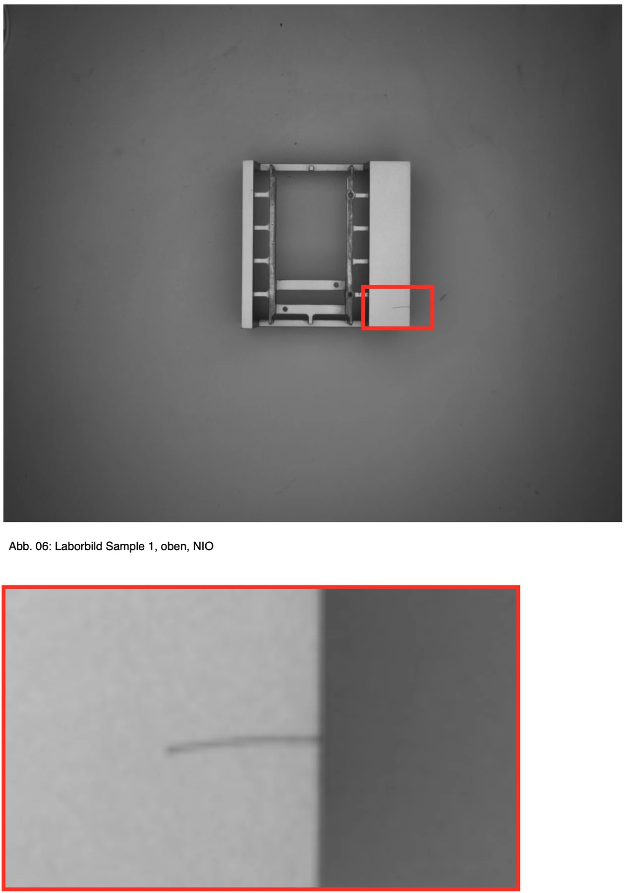 Enlarge the image ↗
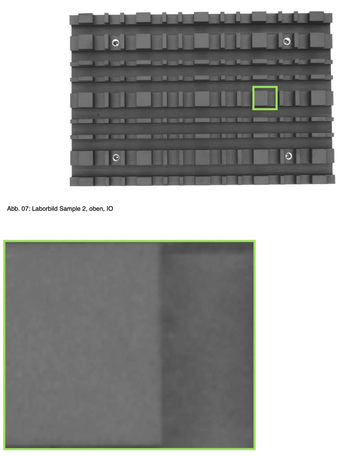 Enlarge the image ↗
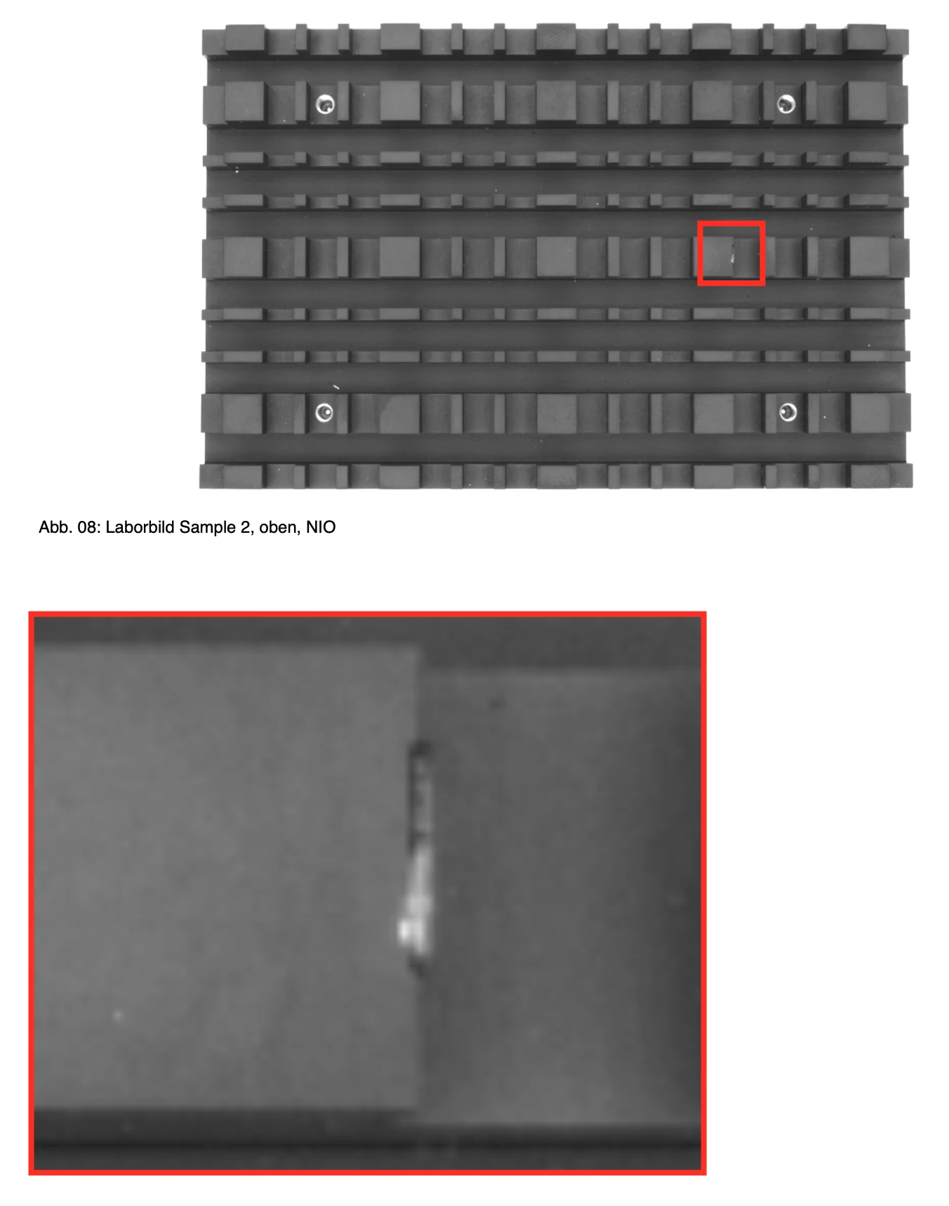 Enlarge the image ↗
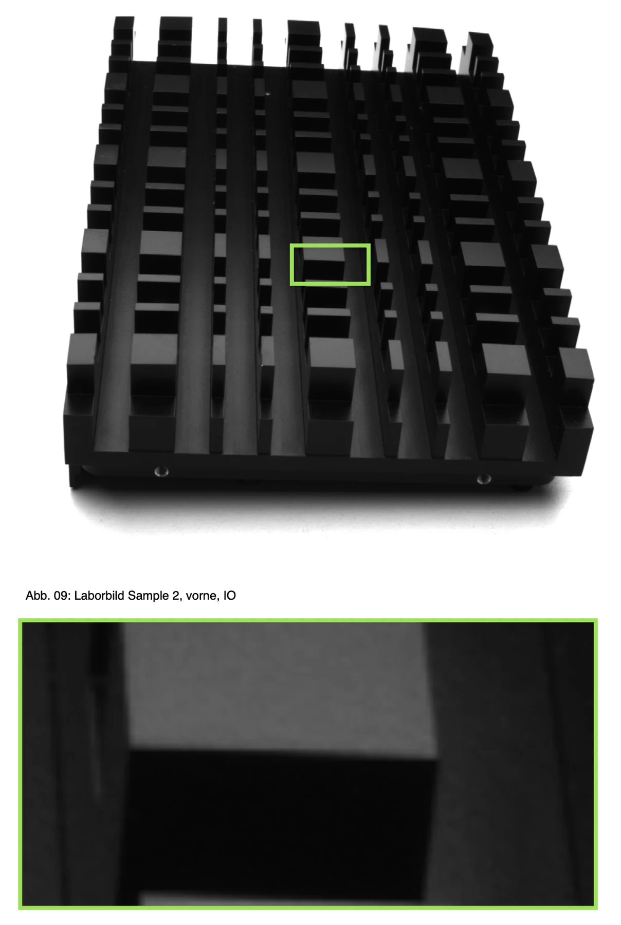 Enlarge the image ↗
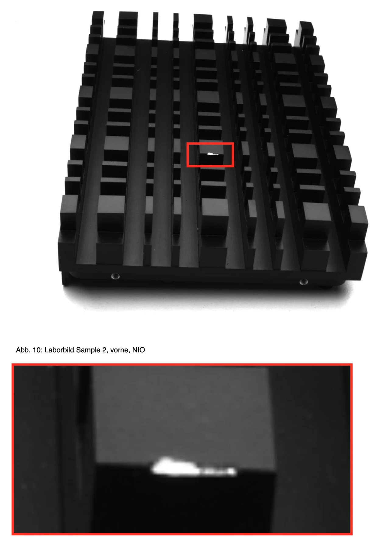 Enlarge the image ↗
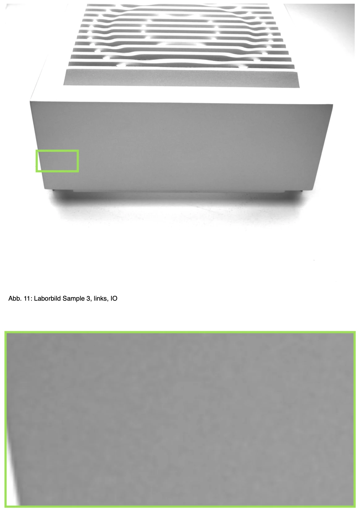 Enlarge the image ↗
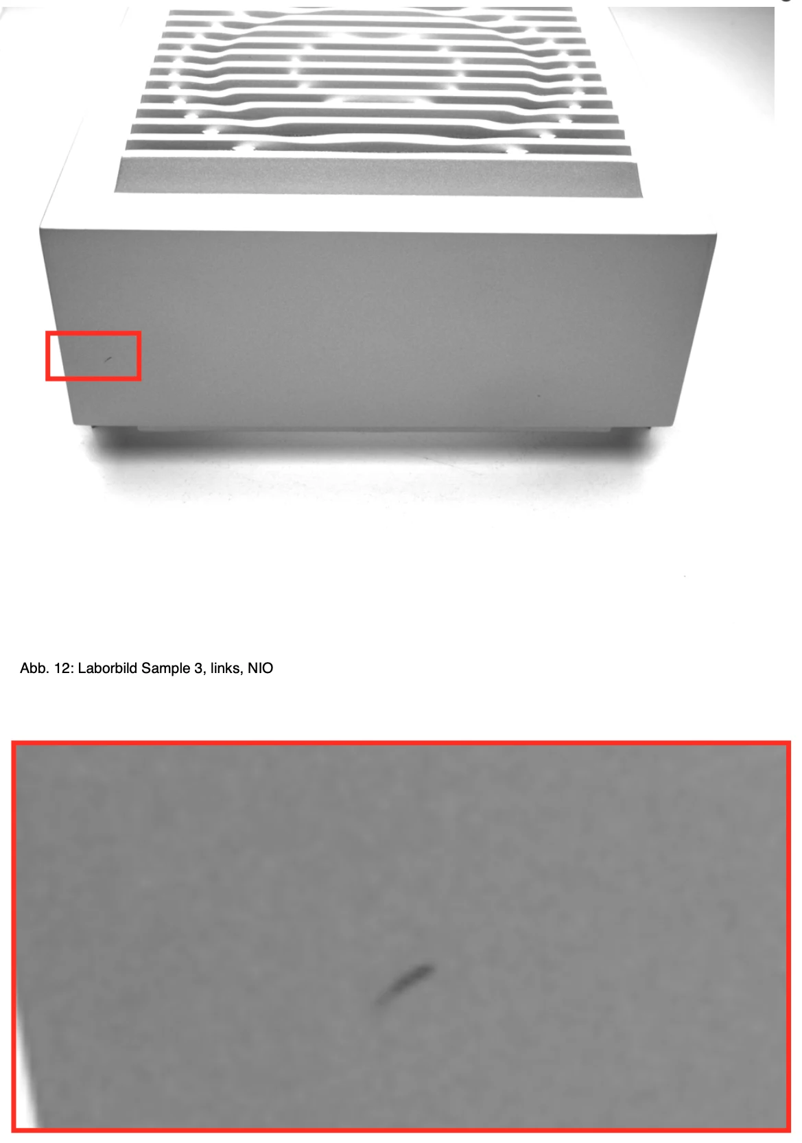 Enlarge the image ↗
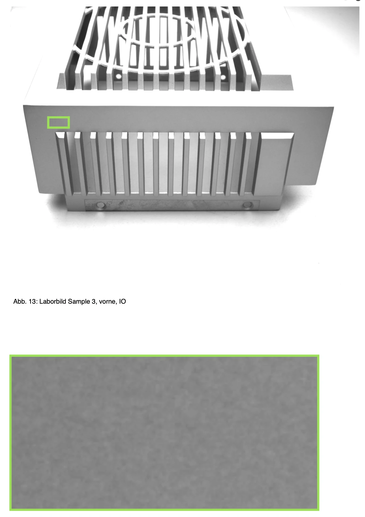 Enlarge the image ↗
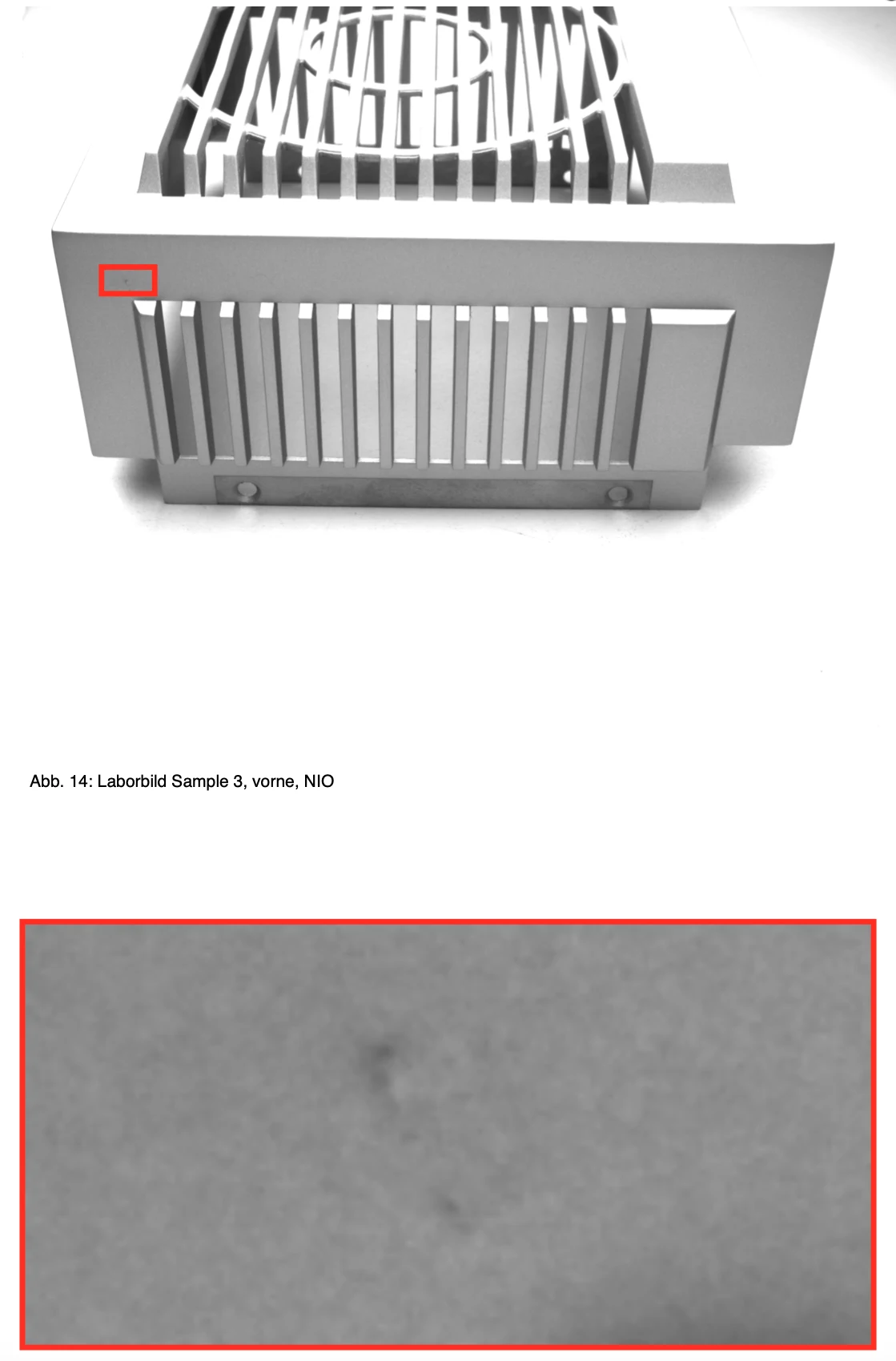 Enlarge the image ↗
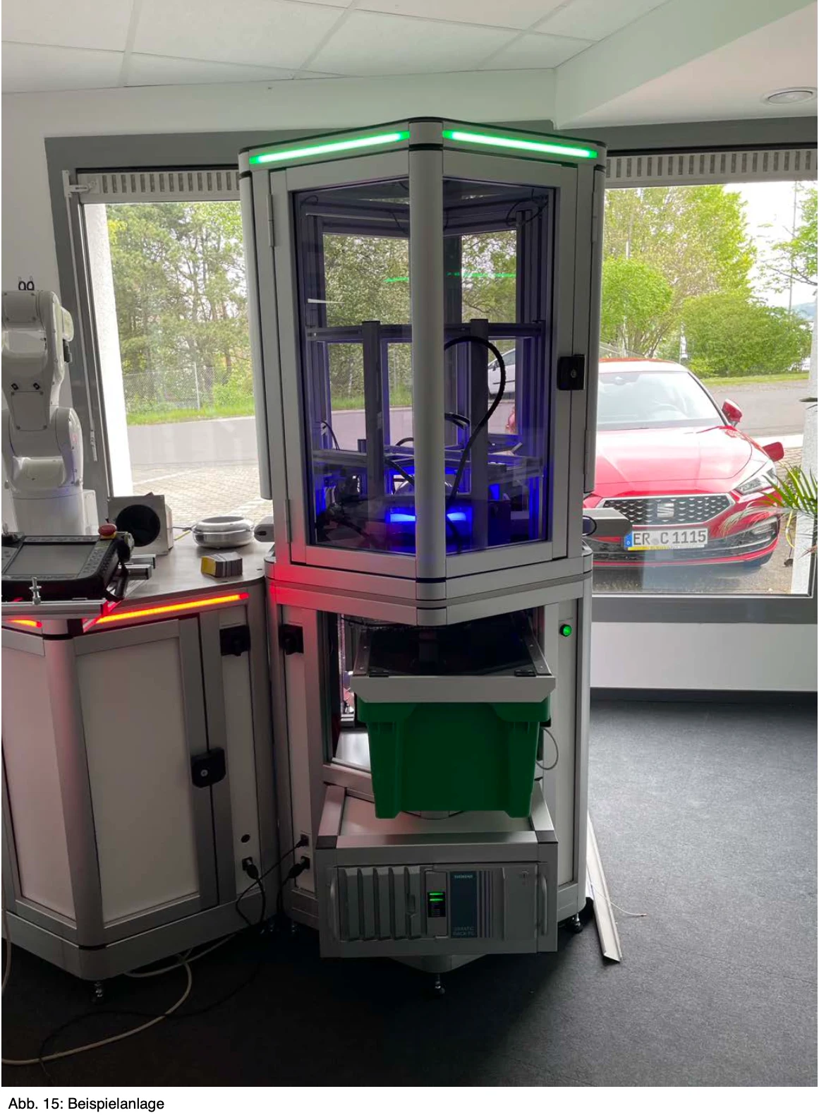 Enlarge the image ↗
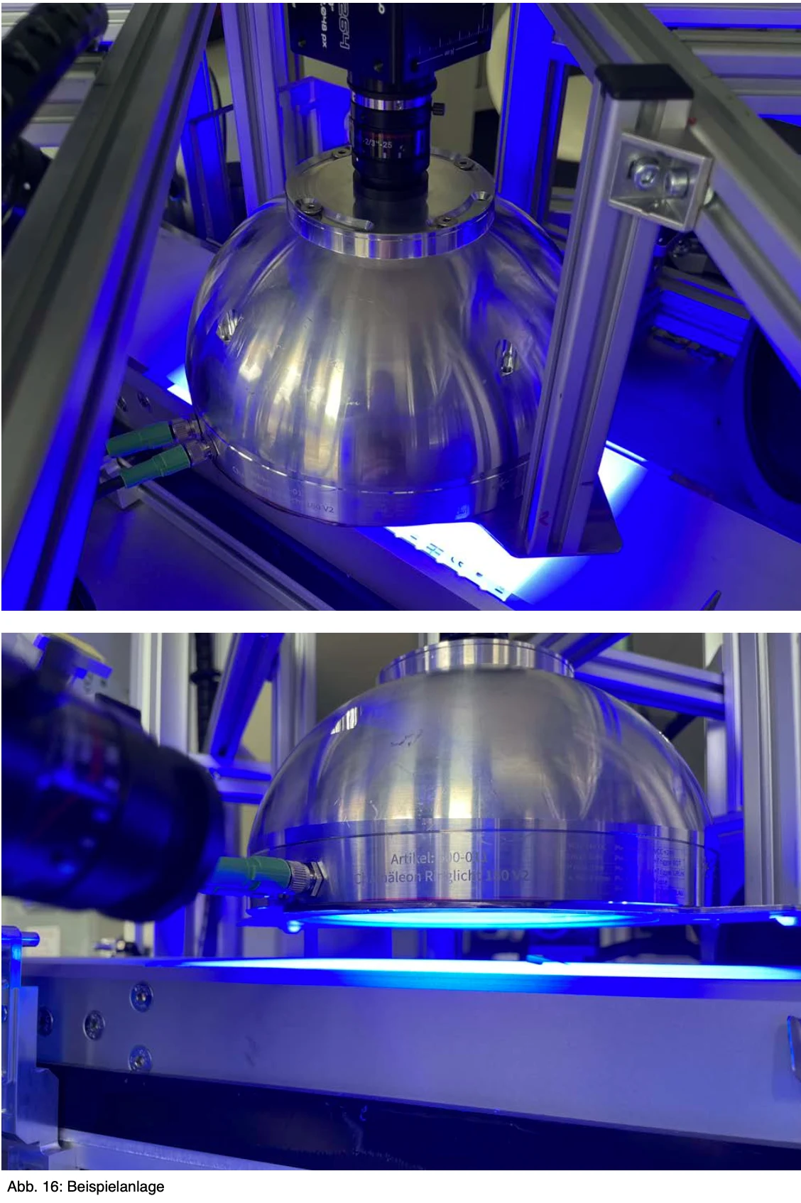 Enlarge the image ↗
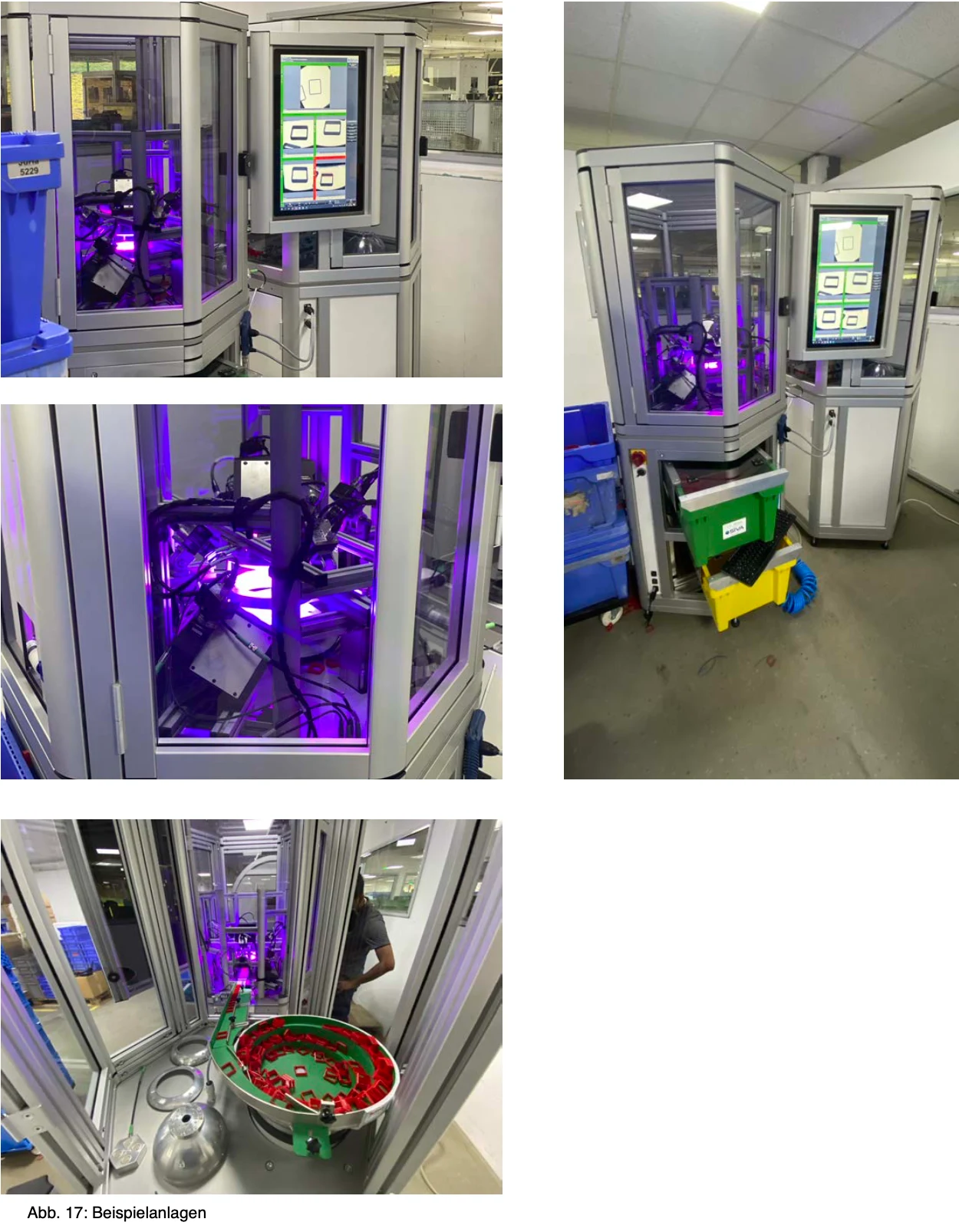 Enlarge the image ↗
Inspection cell for heat-sink surface quality
Project type:
Artifficial Intelligence
Date
2022
Requirement Profiles – Optical Surfaces
Inspection system – task:
The customer plans to purchase an optical inspection system for component surfaces; contour defects and type checks (optional). Five component sides are to be tested simultaneously and the cameras are to be stationary, while the components are to be automatically transported into the test chamber after manual assembly, and then on to the extraction site for manual removal.
Objective:
The aim of this requirement profile is to acquire a complete, operational plant that only needs to be trained/extended to the parts to be tested.
Part size to be tested:
In the design of a part size of
(LxBxH) 150 mm x 250 mm x 150 mm
assuming. The 250 mm should be capable of being transported in width through the test chamber.
Type of test and other functions:
It is an AI-based, optical surface inspection desired, and the machine should be capable of learning.
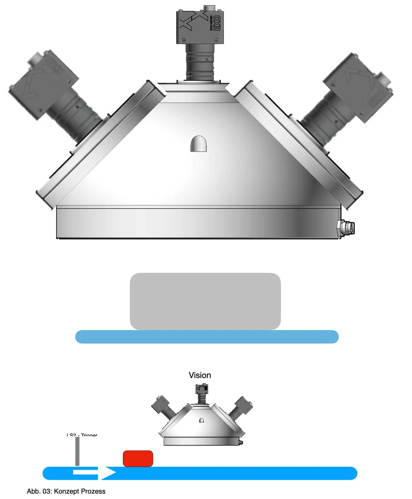
The component should be moved while the cameras should be stationary and all five visible surfaces should be checked in one pass.
Further desired functions are type checks; contour checks (twisting of segments, etc.) and existence checks of elements such as helicoils and bushings.
Monthly number of units:
Monthly quantities of approx. 30,000 parts expected. These shall be tested in single-shift operation with an average working time of 8 hours (40 hours per week). However, the number of pieces is distributed over >50 different parts, and the trend is increasing. Therefore, short set-up and learning times are of great importance.
Machine layout and loading requirements:
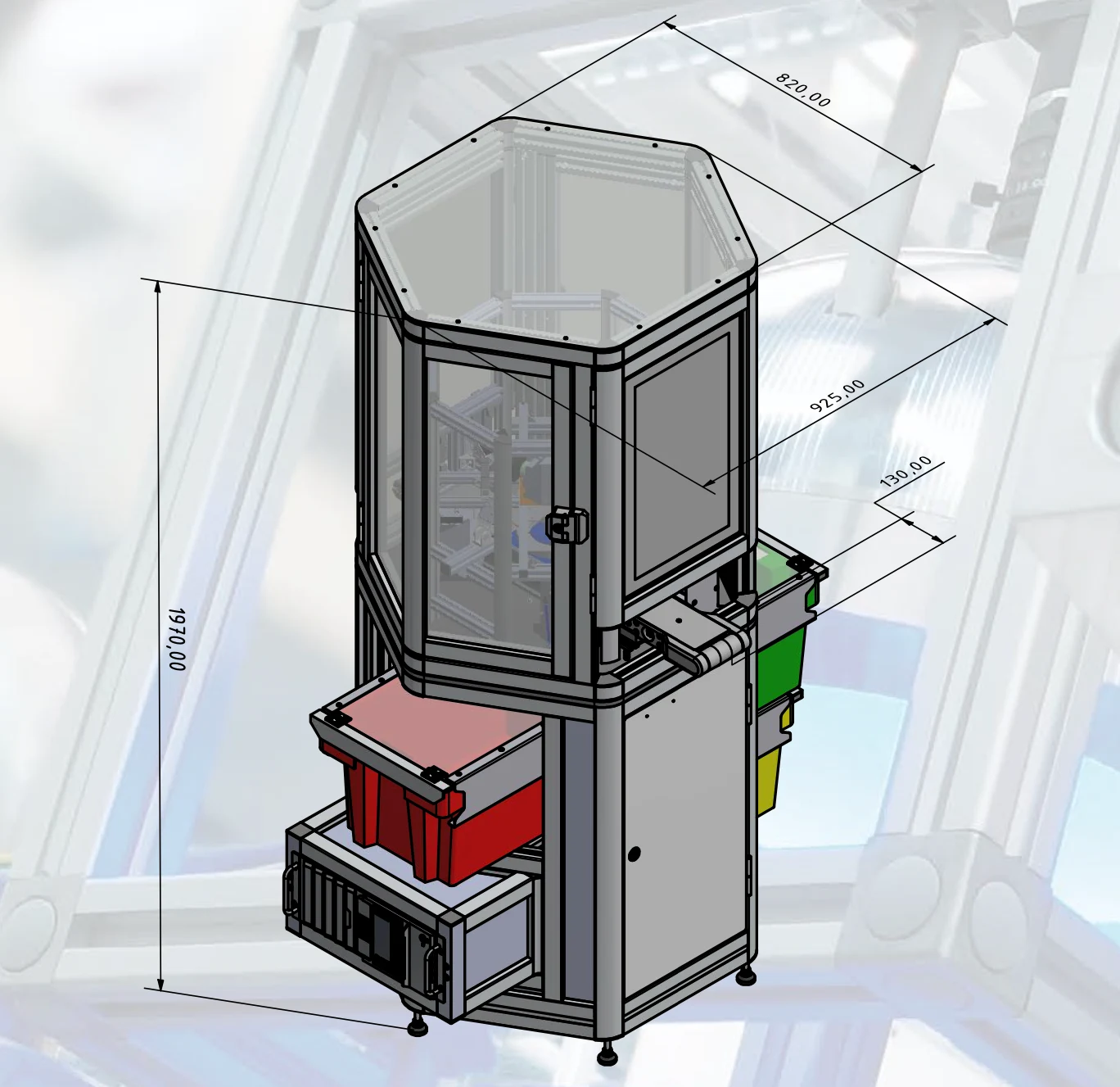
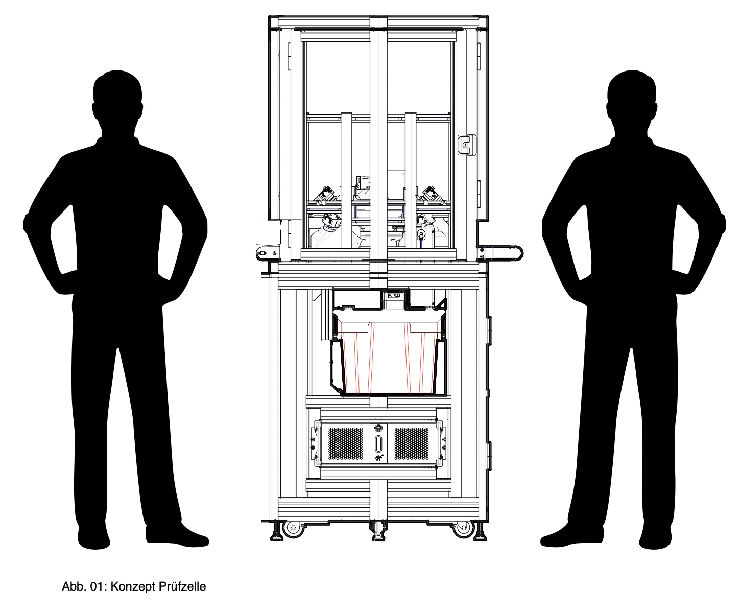
The following machine layout is desired:
Test chamber with cameras
Placement room
The system should be designed to be movable on rollers with locking device. The parts feed into the test chamber and out of the test chamber to the extraction chamber should be designed by means of a belt system. It should be possible to equip the belt system from both longitudinal sides of the installation. Depending on the possibilities, the tape system can be designed both continuously and in a start-stop version (clocked tape).
In addition, an adjustable lateral guide should be provided in the fitting space, which allows the same positioning of the components under the camera system.
Furthermore, in the case of a part jam in the removal chamber, the belt operation is to be stopped and an optical representation is to take place.
Surface types to be tested:
The plant is intended to test technical surfaces:
• Painted surfaces (mainly silver and black)
• KTL coated surfaces (mainly black)
• Anodized surfaces (mainly silver and black)
It is desired that the system independently checks surfaces to a certain extent, but it is accepted that specular or glossy polished surfaces are excluded.
Types of errors to be expected:
During the tests, it shall be assumed that the following types of defects may occur:
• Paint scratch
• Lunker/ Material Defects
• Paint flaking
• Contour errors (malfunctional grinding, excessively rounded edges, bent and twisted elements, grooves, burrs)
• Irregular colour gradients/painting defects/shades
Optical representation of the inspection result:
The inspection result should be visually displayed, ideally by means of a three-step system in which clear good (green), clear bad (red) and parts requiring further assessment (orange) are distinguished.
Extensibility requirements for the audit portfolio:
The system should be able to be independently extended, after appropriate training, by further components to be tested. Furthermore, additional errors should be easy and self-programmable, and should also be able to be transmitted between parts. It would also be desirable to weight errors and different categories of areas (critical, less critical, uncritical).
Documentation:
The installation shall be provided with a user manual which includes both the operation of the installation and the correction of possible errors.
Commercial:
The following points should be taken into account when submitting a tender:
• Acquisition costs of plant and software (one-off)
• Maintenance costs annually plant
• Maintenance costs annually Software/Support
Viewing angles of the cameras:
90° from above 45° front
45° Rear side 45° Link
45° to right
Yield 90° to the left. 90° to right
DO NOT TEST BETWEEN
Request for this application →