
Publication archive
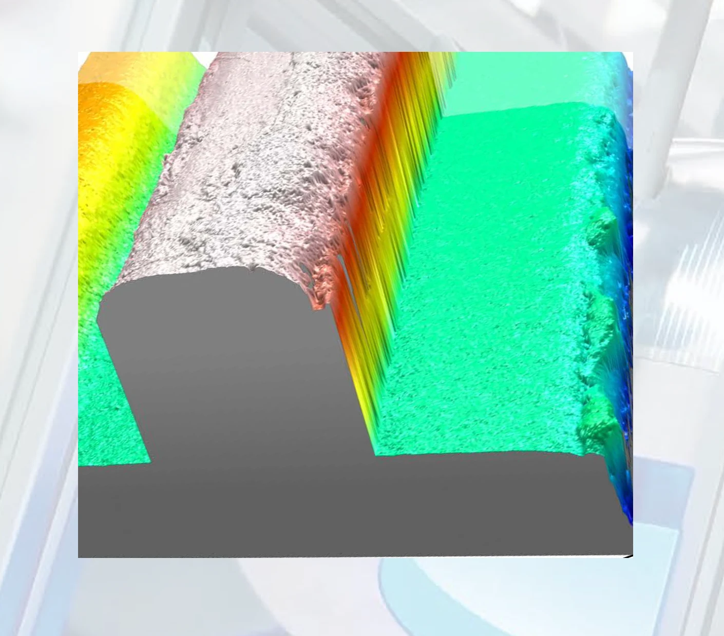
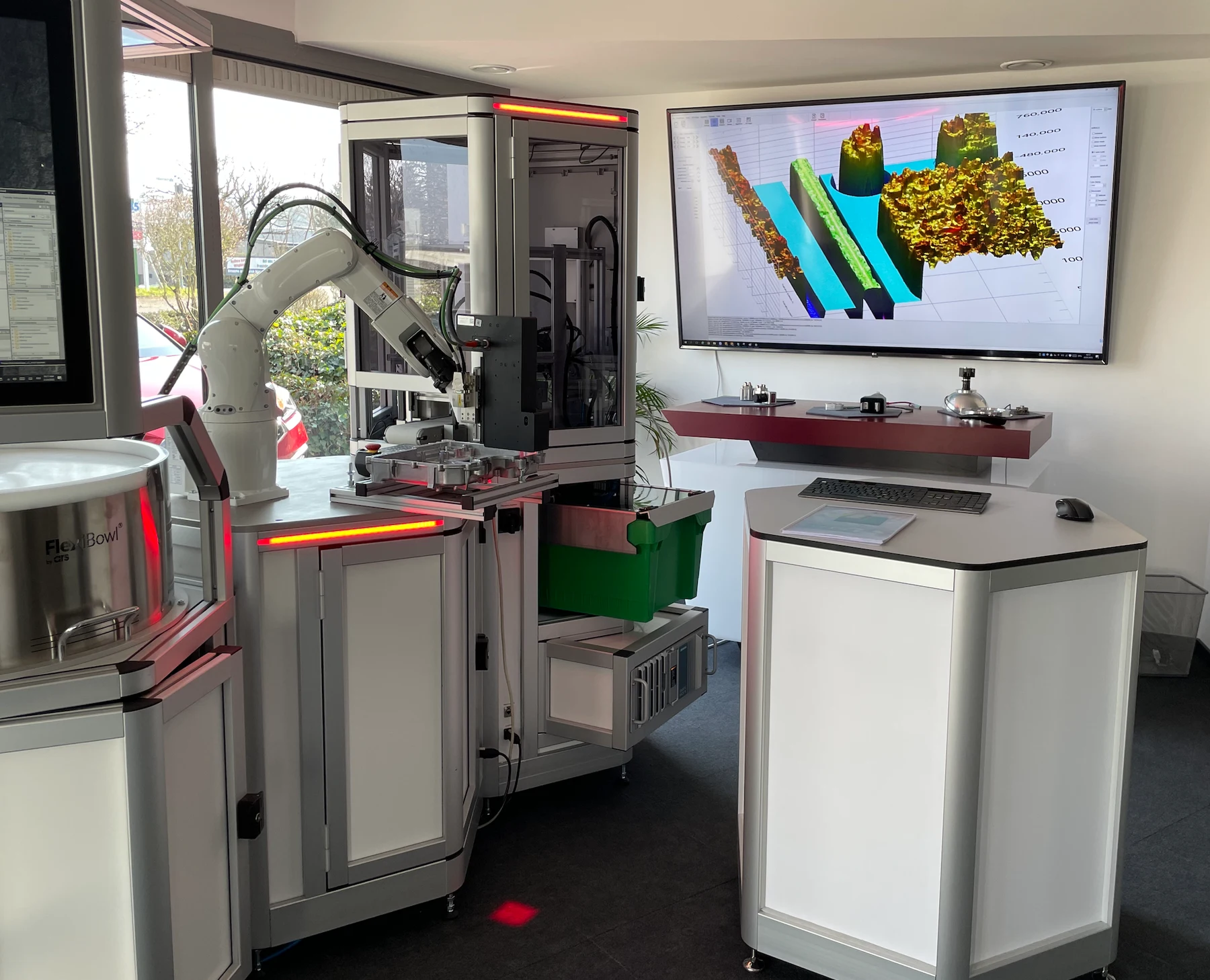
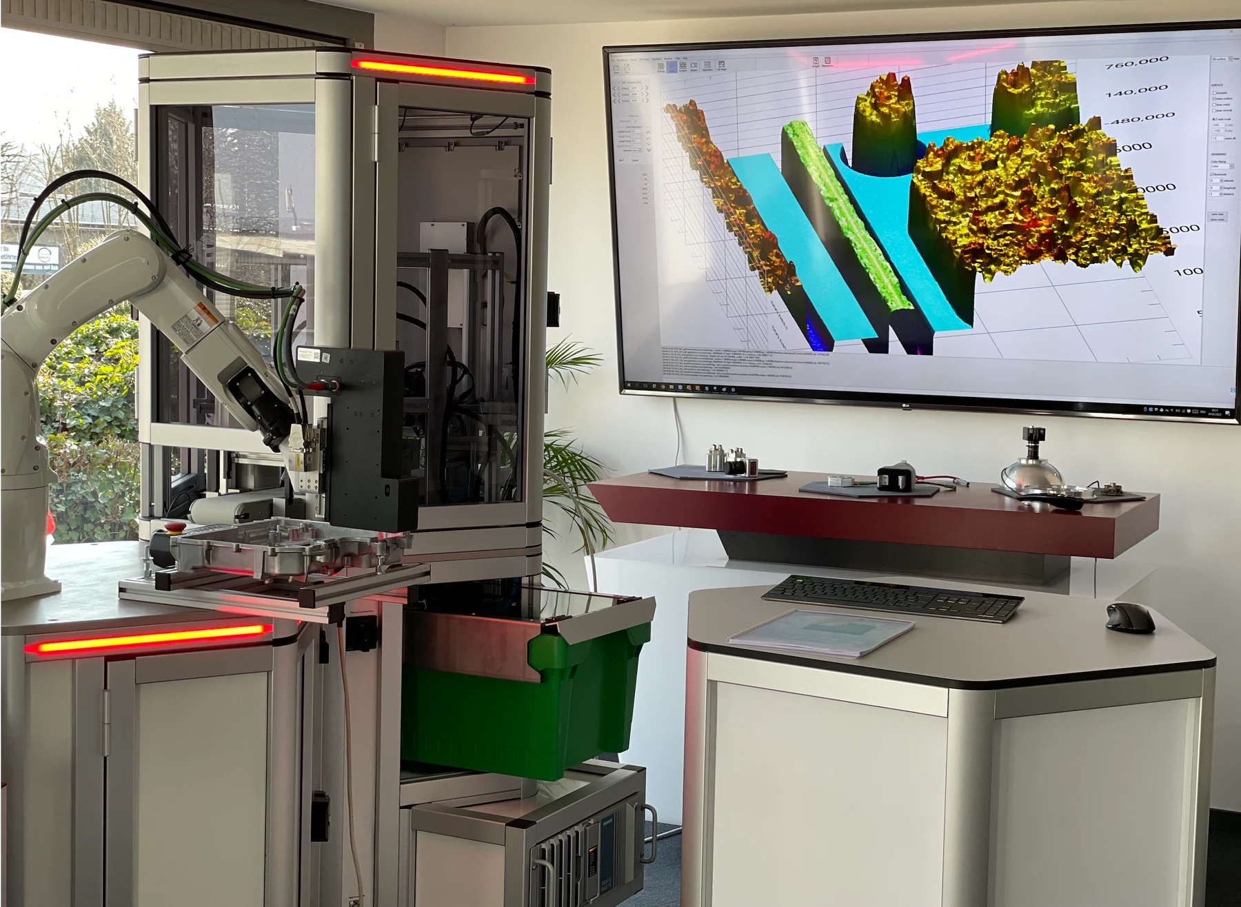
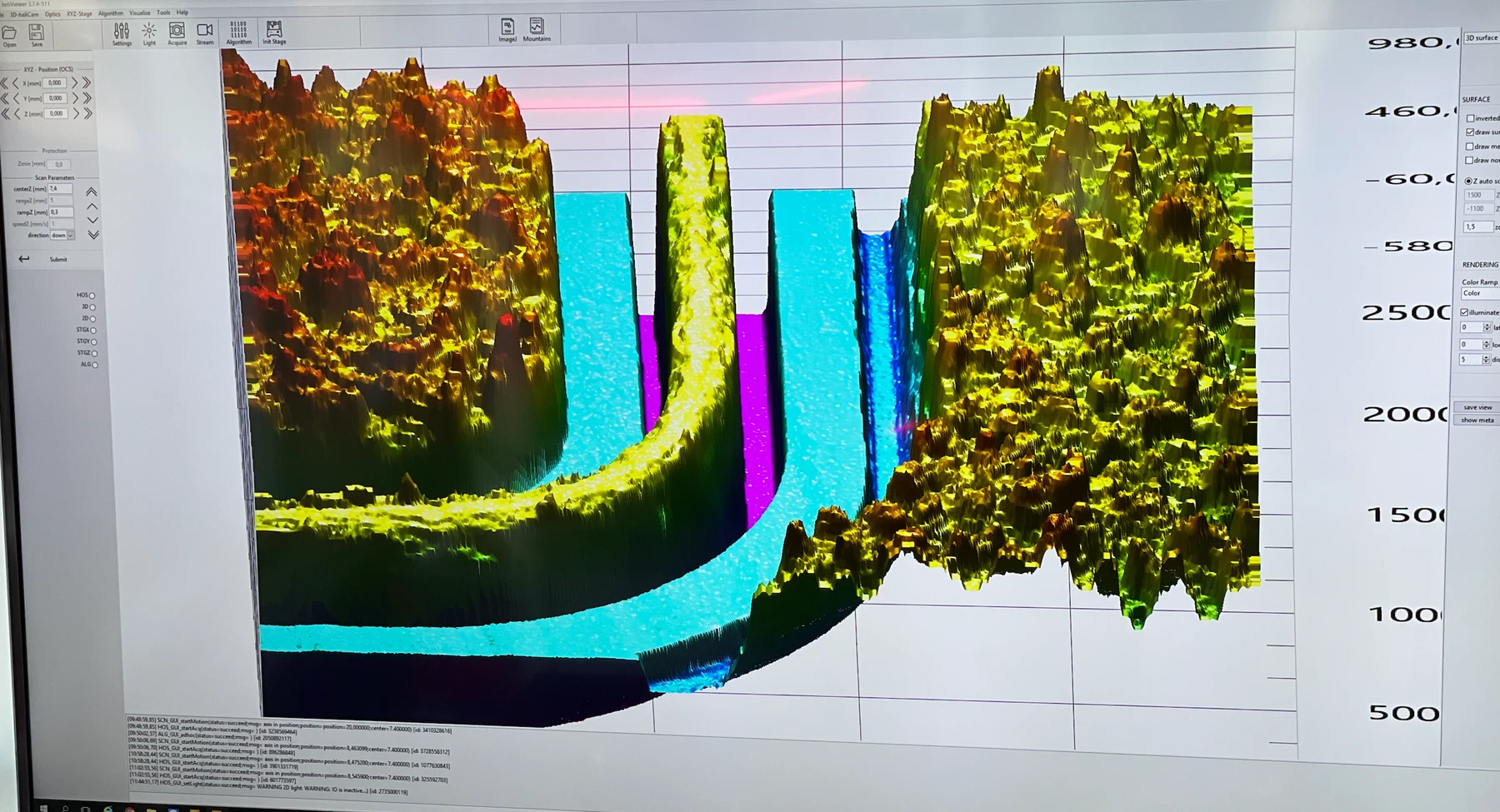
3D measurement and inspection of transparent adhesive beads using white-light interferometry
Insight into a published application or lecture from the CRETEC archive.
Archive content: Information refers to the original publication status. Please coordinate current execution, scope of services and availability with CRETEC.
 Enlarge the image ↗
 Enlarge the image ↗
 Enlarge the image ↗
 Enlarge the image ↗
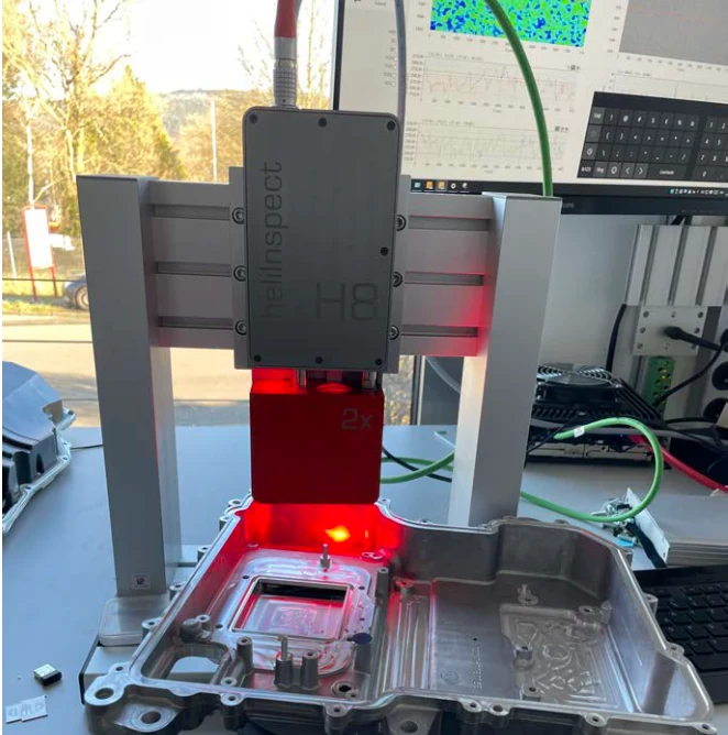 Enlarge the image ↗
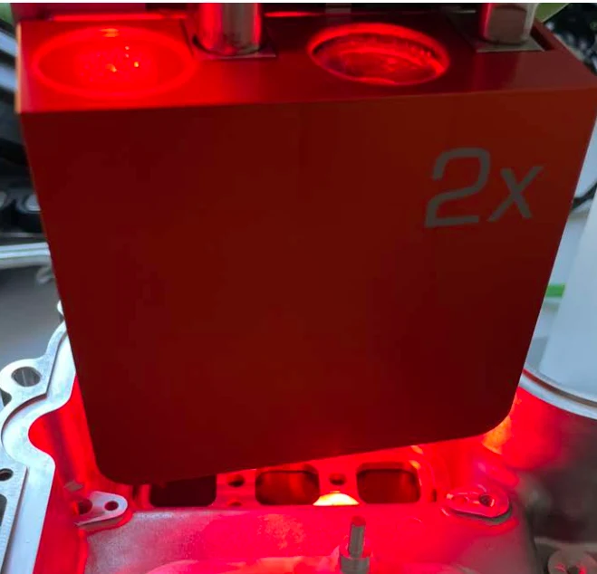 Enlarge the image ↗
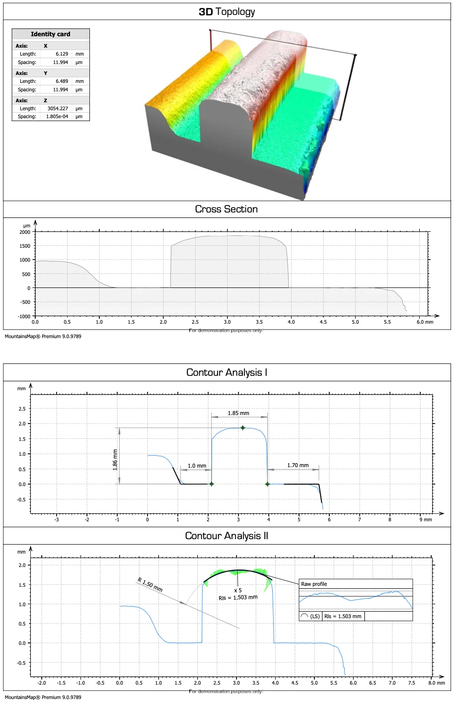 Enlarge the image ↗
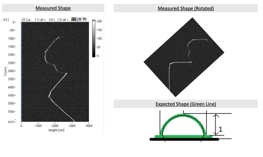 Enlarge the image ↗
 Enlarge the image ↗
 Enlarge the image ↗
 Enlarge the image ↗
 Enlarge the image ↗
 Enlarge the image ↗
3D measurement and inspection of transparent adhesive beads using white-light interferometry
Project type:
Automotive
Date
2022
1 - Requirement
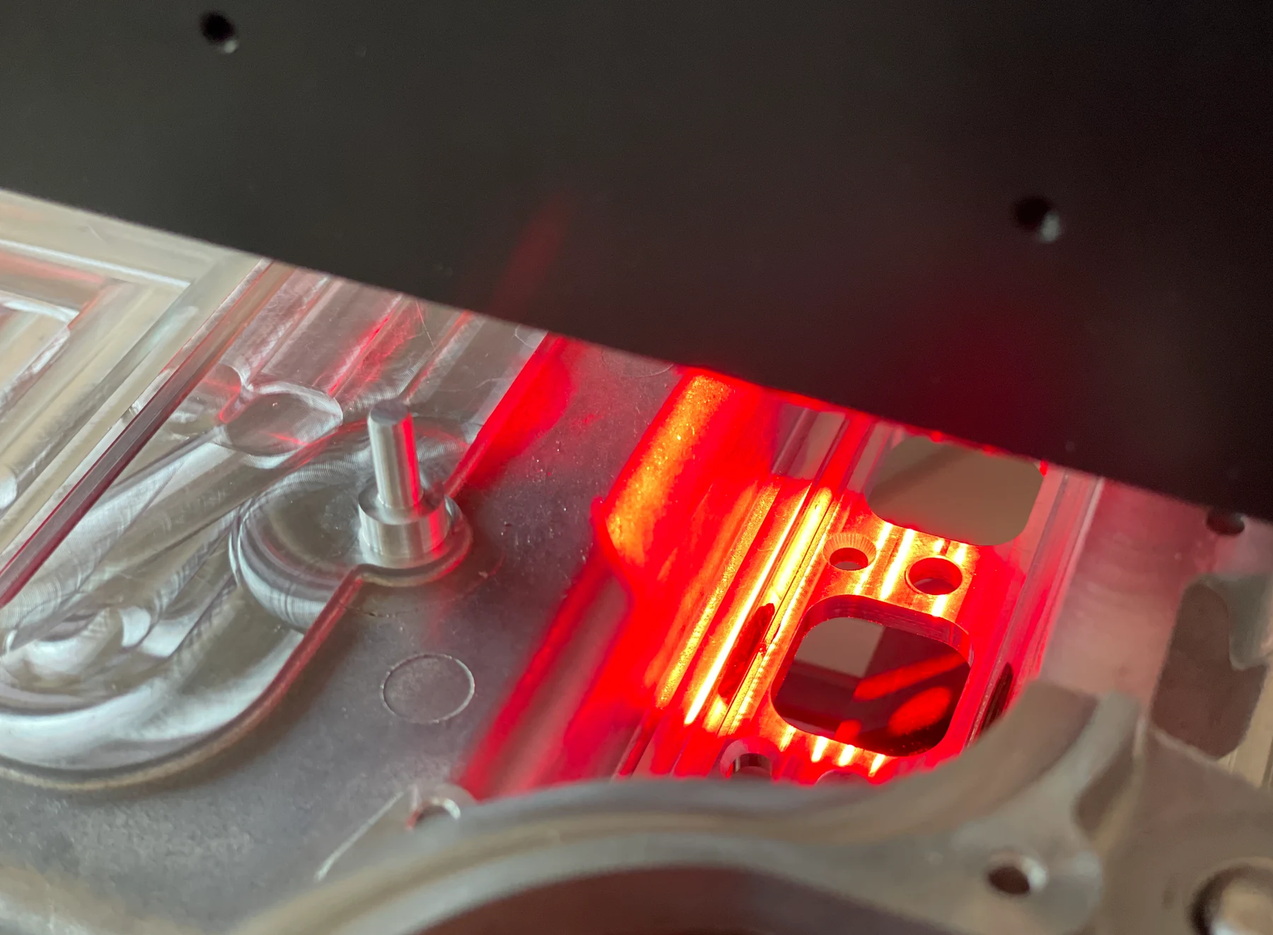
Inspection scope is the correct design of the seal dispensed onto the housing edge of an aluminum die-cast housing.
The sealing function of the seal with respect to the cover is produced by compressing the seal onto the housing when pressing down and screwing the cover.
This seal must therefore be checked in a contact-free manner.
Important features for correct execution are
the position, or web in which the seal has been glued to the housing,—the sealing height, and
- the width of the seal.
1.2 - Inspection system
a) The test of the seal takes place after the hardening of the seal.
b) The housing with the disintegrating seal has already passed through the hardening section at this time.
The seals are hardened under UV light.
c) The test device settings (limit value specifications, variant selection) are freely adjustable and secured against unauthorized adjustment (password protection).
At the time of checking, the current area should be displayed on a screen.
d) The test status is stored for each item in the traceability system with: - date, time
- Error code and location (position on sealing sheet)
- Unique number (serial number from data matrix code on housing)
e) After detecting 3 subsequent errors, the system must show an error message or come to a standstill. The interval shall be adjustable by an extended operator.
f) The test shall be carried out as described in point 6.
g) The test should function similarly to a solder paste inspection (SPI) based on the principle of modulated strip projection in order to be able to capture the shape and dispensed quantity cleanly above the housing edge.
1.3 - Marking test status
1.3.1 -> n.i.O. Parts
Defective parts are automatically discharged into a separate bad part magazine. The marking of the test status is done via the traceability system, see point 2f. In addition, an defect appearance is stored which can be assigned to the defective individual part.
3.2 -> follow-up of niO. Parts
The follow-up control and decision on pseudo or real errors is carried out subsequently by an operator. The inspection system shows the operator the recorded defect appearance at a verification site to match the part under inspection. An event. Overmatching of the defect appearance by the operator must be documented electronically at the verification station. The result of this decision shall also be deposited in the traceability system.
The verification location required for this purpose is the scope of delivery of the test device.
1.4 - Process locking / traceability
After the test, the measurement data with test parts identifier are stored in a database. In this case, the testing device transfers the inspection results to a quality data acquisition computer. In this case, a data matrix code already present on the product is read in. Using this data matrix code and the database, an exact test data assignment to the individual component can be traced at any time.
1.5 Part under inspections
1.5.1 Overview of variants
The inspection system is intended to process different variants of dispensed housing seals.
may be: Currently, however, there is only one valid variant:
1. Housing for type 0001
The active housing variant can be selected on an operator surface. Variant overview / Inspection areas are agreed/submitted later. The conformity of the chosen variant with the DMC shall be checked.
1.6 Test of the seal/sealing contours
1. Seal height: 1,75 ± 0,2 mm
2. Seal width: 2,0 ± 0,2 mm
3. Sealing profile: defined in drawing
3.1 Distance from the edge of the housing: tbd
3.2 Sealing form: tbd
3.3 Sealing volume: tbd
4. Data Matrix Sticker (DMC): Readable DMC -> YES or NO
1.7 Error indicator / error detection / interface CAQ program
a) The current defect images of the housing seals shall be displayed online on a screen.
b) The respective inspection result is currently readable on the monitor.
c) A number counter for i.O. / n.i.O parts must be displayed on the monitor.
d) All test data and images are stored individually for the respective housing with the associated unique number on a network drive, so that they can be called up and evaluated at the analysis site or in the event of a later complaint.
1.8 - Test accuracy
a) A demonstration of capability shall be provided by the manufacturer. The ability for positioning and for gray values is demonstrated on the basis of a geometrical and a gray value calibrate and its testing over 50 runs.
b) The following tolerances T apply:
Positioning: +/- 20 μm orthogonal view
Gray scales: +/-5 gray scales
1.9 - Calibration standards
The calibration standards are the geometrical calibration plate and the gray scale value plate of the manufacturer. In this way, comparability of different machines and long-term stability can be achieved.
The calibration standards are provided by the customer
1.10 Other
a) The test equipment shall be designed in such a way that no mechanical damage can occur. Any impairment with respect to Optics of the part under inspection (damage, contamination, surface structure, color, ...) by the testing process is not allowed!
b) An operating and calibration instructions shall be provided for the test equipment.
c) The operating software has an operator and a password protected
Expert mode.
d) Form FB-721 034 is completed by the supplier.
Request for this application →