
Publication archive
Quality inspection of electric-vehicle busbars
Insight into a published application or lecture from the CRETEC archive.
Archive content: Information refers to the original publication status. Please coordinate current execution, scope of services and availability with CRETEC.
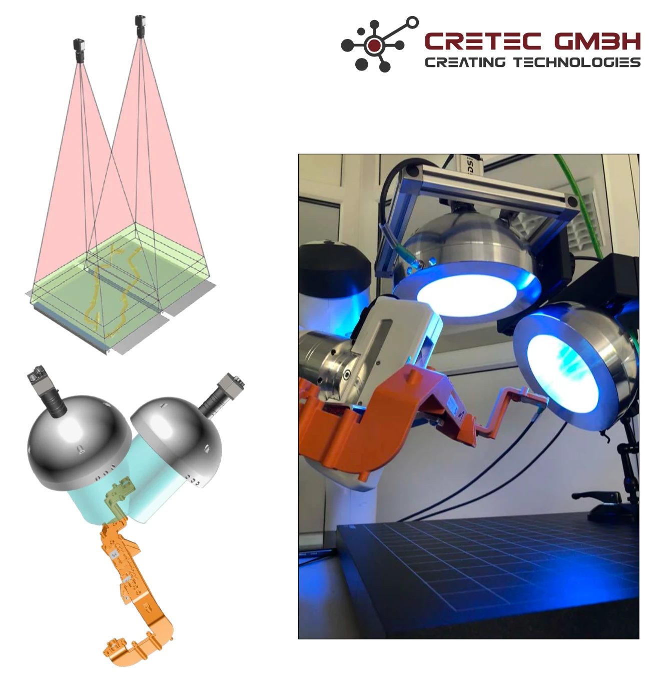 Enlarge the image ↗
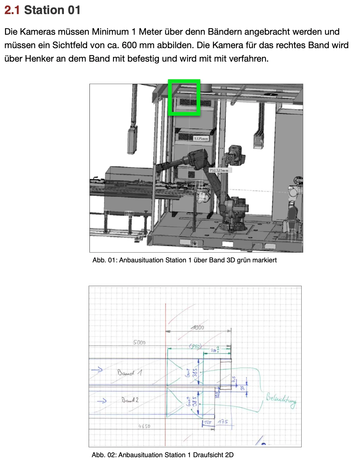 Enlarge the image ↗
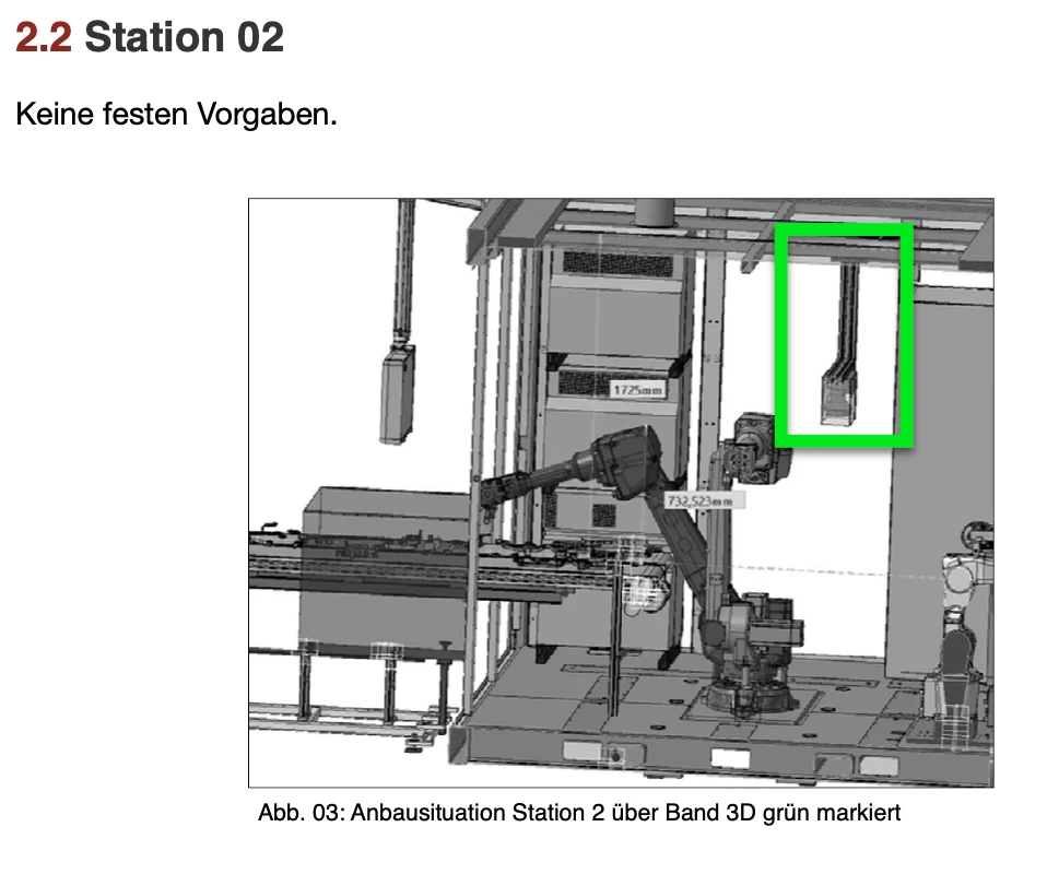 Enlarge the image ↗
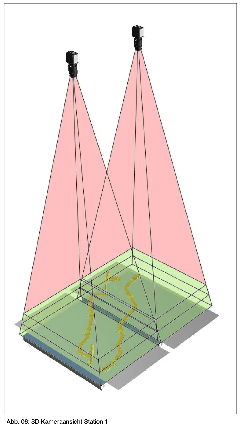 Enlarge the image ↗
 Enlarge the image ↗
 Enlarge the image ↗
 Enlarge the image ↗
 Enlarge the image ↗
 Enlarge the image ↗
 Enlarge the image ↗
 Enlarge the image ↗
 Enlarge the image ↗
 Enlarge the image ↗
 Enlarge the image ↗
 Enlarge the image ↗
 Enlarge the image ↗
 Enlarge the image ↗
 Enlarge the image ↗
 Enlarge the image ↗
 Enlarge the image ↗
 Enlarge the image ↗
Quality inspection of electric-vehicle busbars
Project type:
Automotive
Date
2018
1 - Requirement
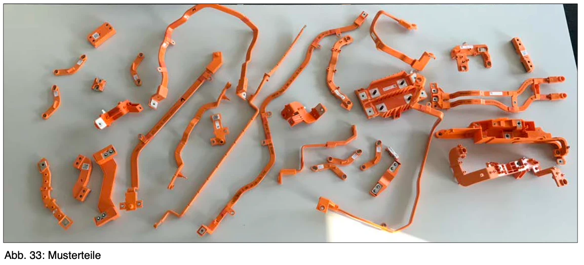
The customer builds a system that evaluates 43 components for optical, mechanical and electrical condition. The optical control is divided into 4 stations (3 physically different).
The PLC combines the inspection results. The end customer has not specified defect dimensions; the task is inspection and verification, rather than measurement.
Each component has different inspection criteria.
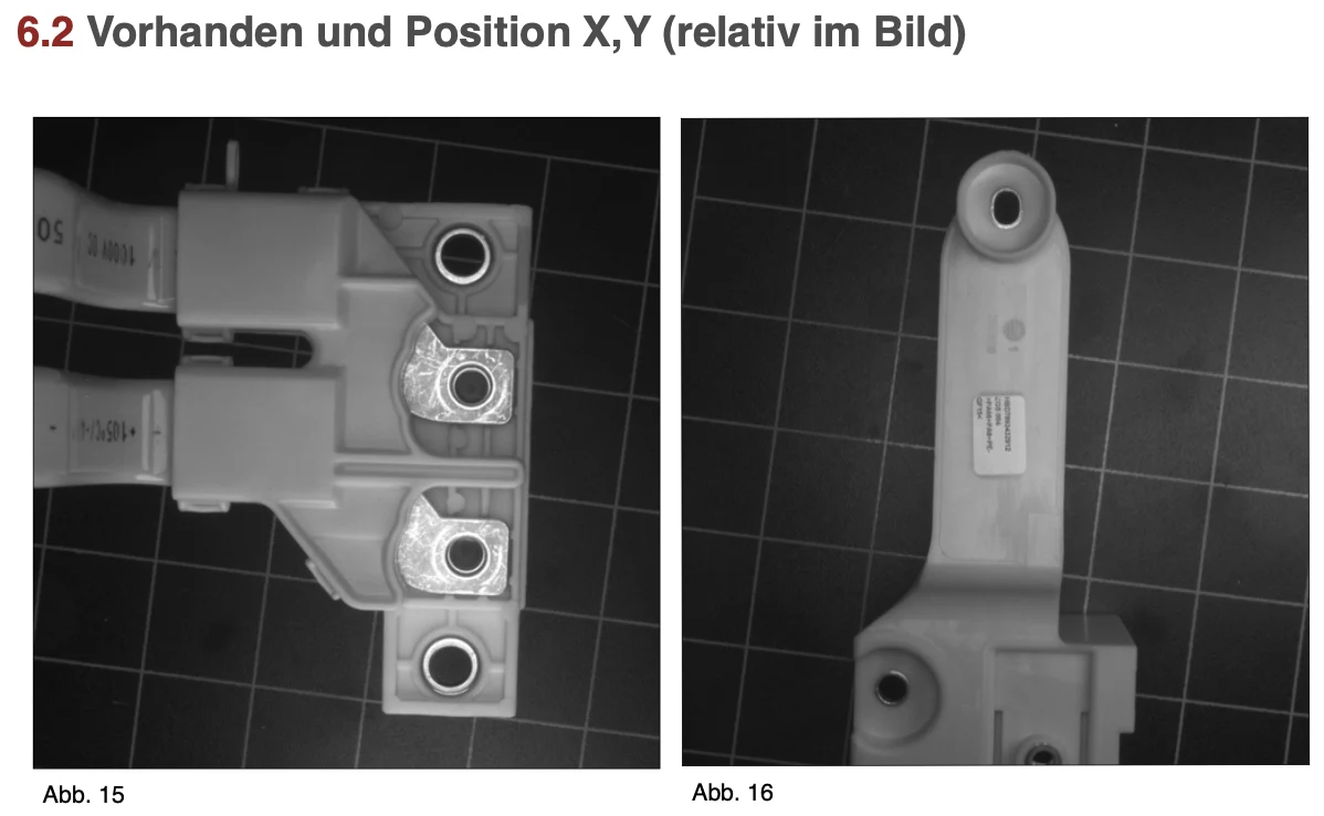
In total, these can be divided into 8 basic examinations: • Presence and position X,Y (relatively in the picture)
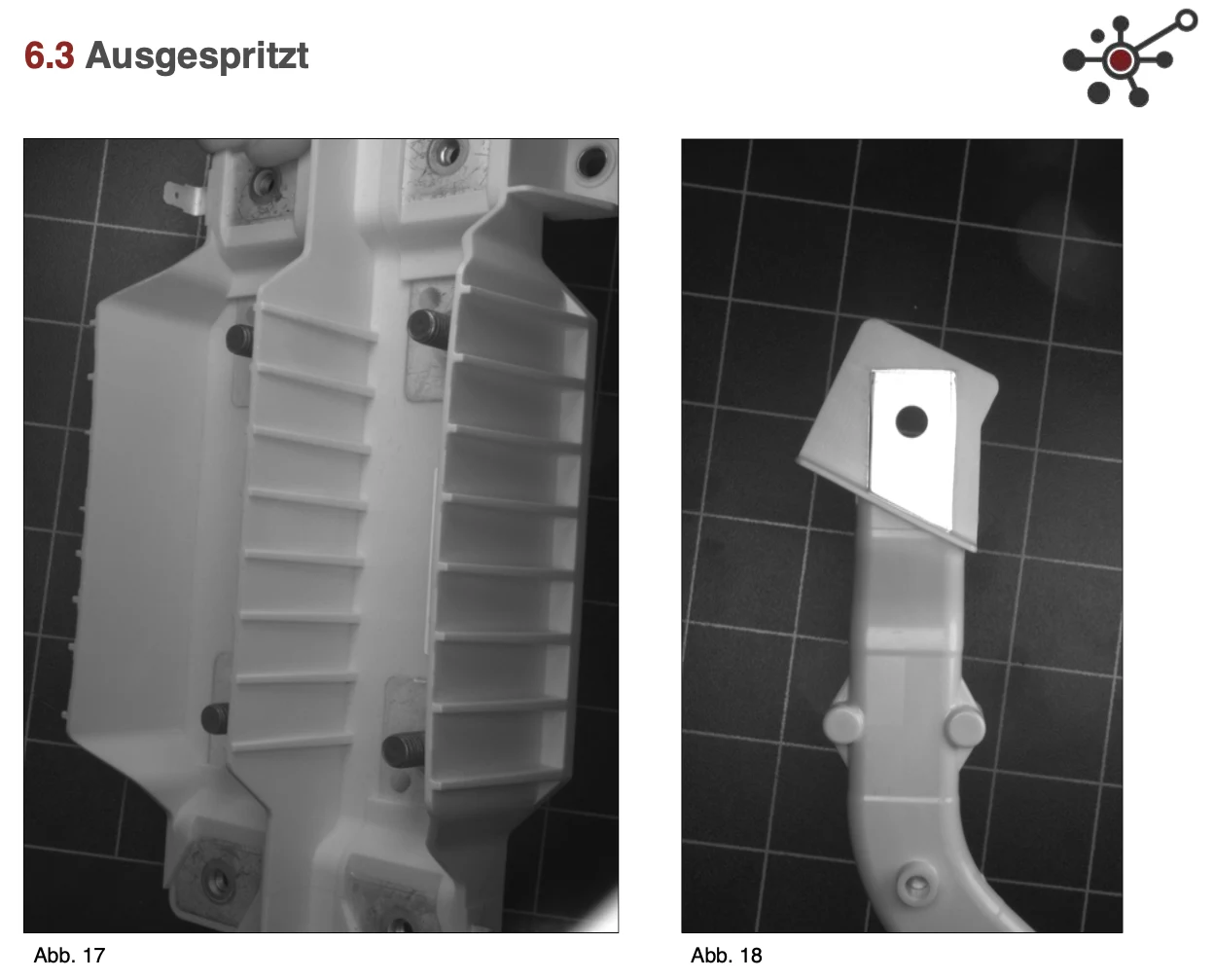
• Injected
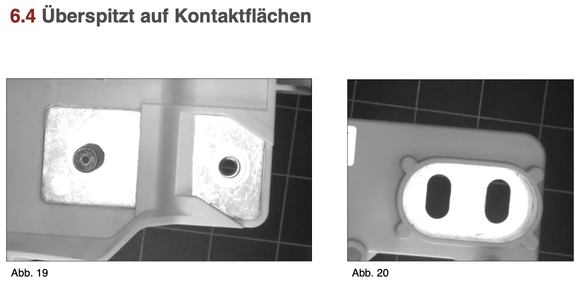
• Excessive on contact surfaces
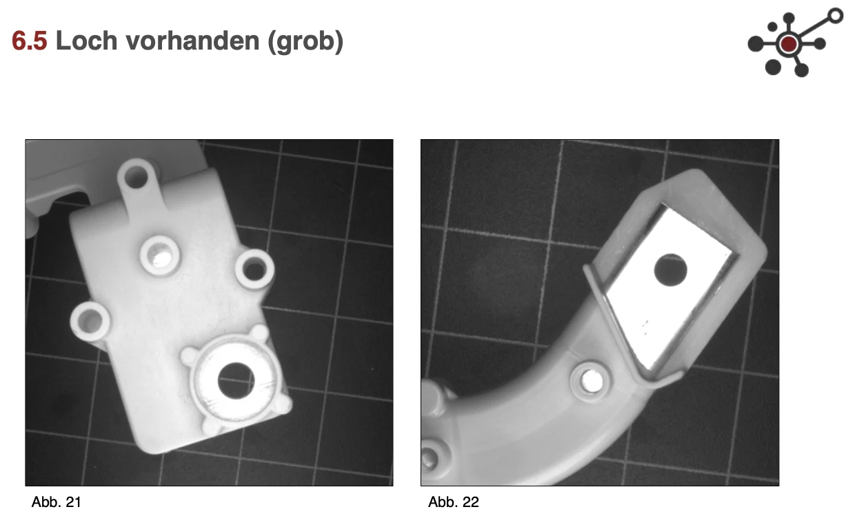
• Hole present (roughly)
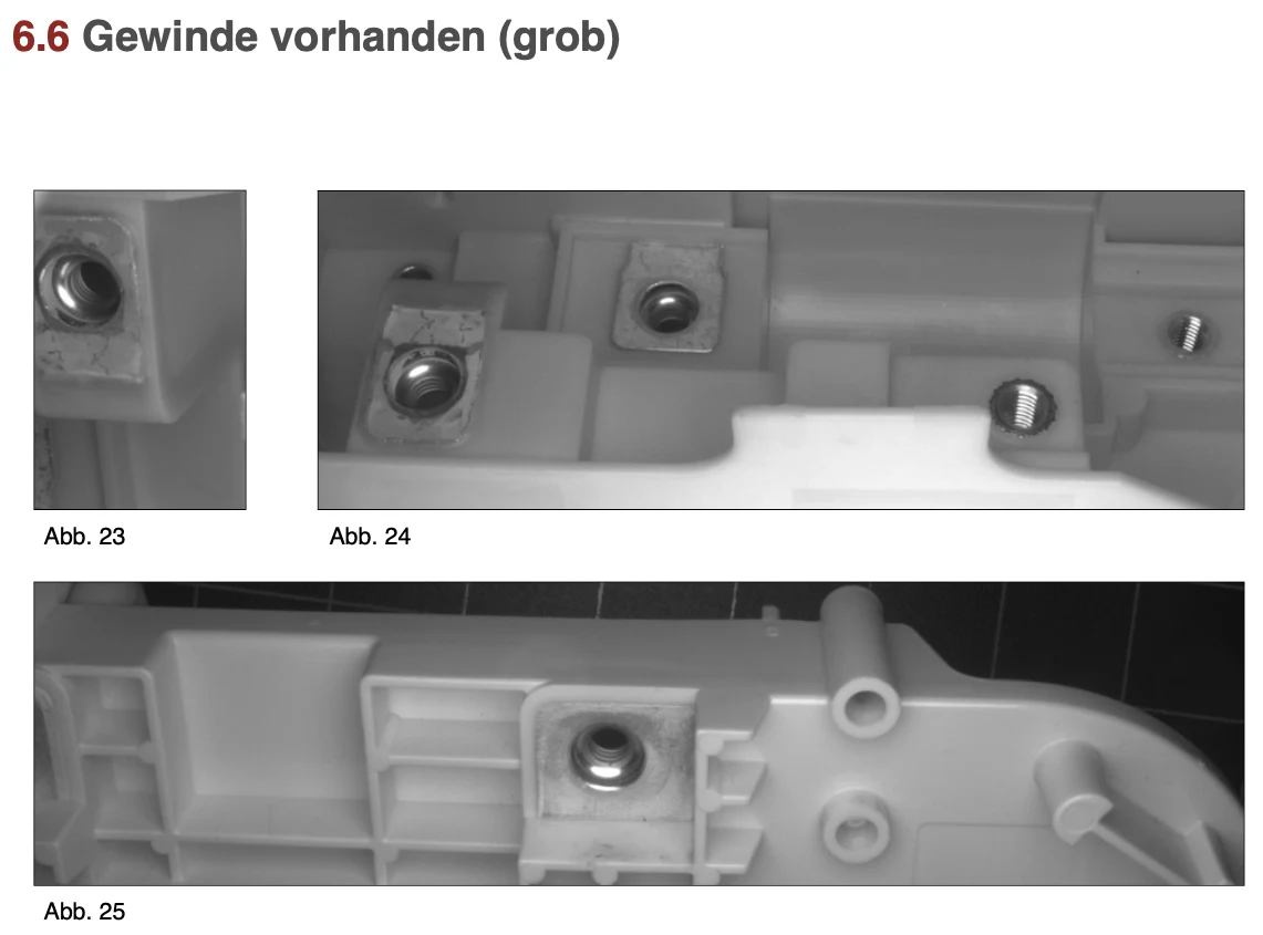
• Thread present (roughly)
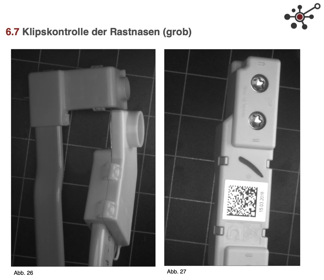
• Clip control of the latching lugs (roughly)
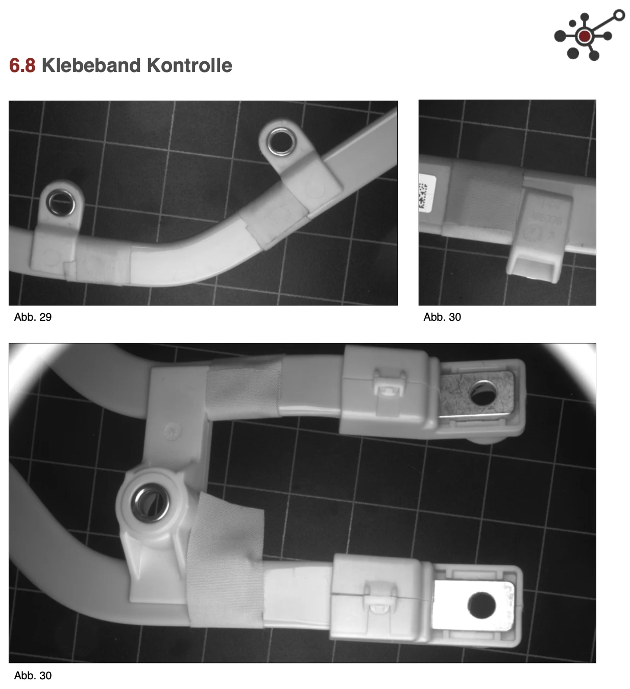
• Tape control
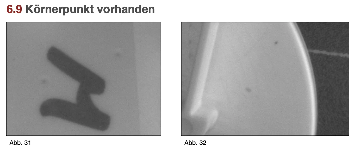
• Grain point present
1.1 - Station 01 - Position detection
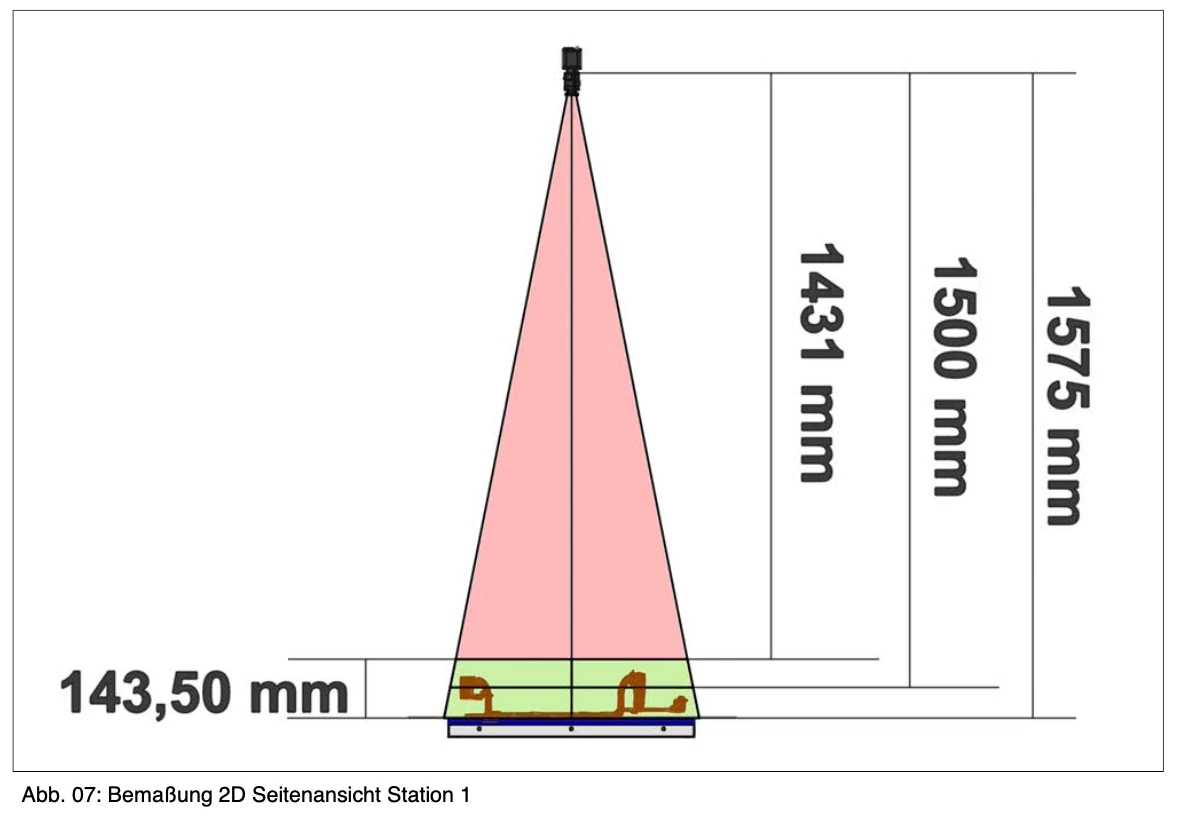
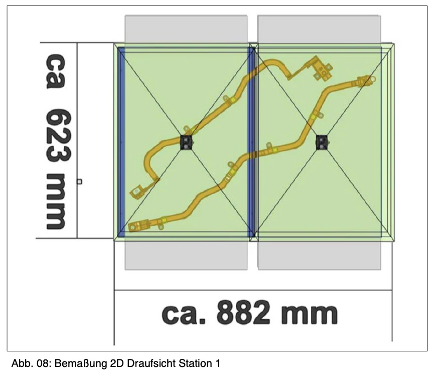
The component positions are detected optically via the camera system. The parts under inspection are located in station 1 on 2 belts.
Due to the component shapes, the right (short) strip can be moved downwards 250 mm. One camera is used for each band. The camera on the right (short) tape is moved along with it.
The images of the two cameras are combined to form an image and this is calibrated with the robot coordinate system. The accuracy of the position determination should be +/−1 mm.
Exemplary test sequence at station 01:
1. Optical system gets a trigger every 10 cm
2. Once a component or unknown mass is completely in the picture (run-in edge will no longer be
is touched), the optical inspection system outputs the message that something on the tape has been detected
has been.
3. After an unknown time X (following the tape), the trigger is executed again
to verify the position again for robotics.
4. Component is gripped according to the detected position
The nature of this process comes about because the tape has a certain follow-up time when braking, so a normal “start/stop/trigger” behavior would cost too much cycle time.
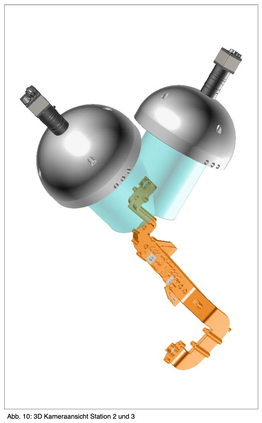
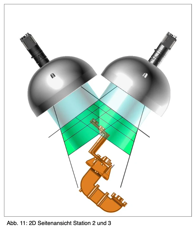
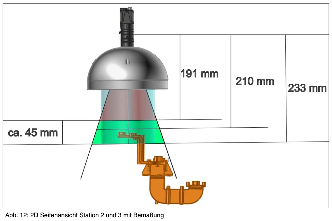
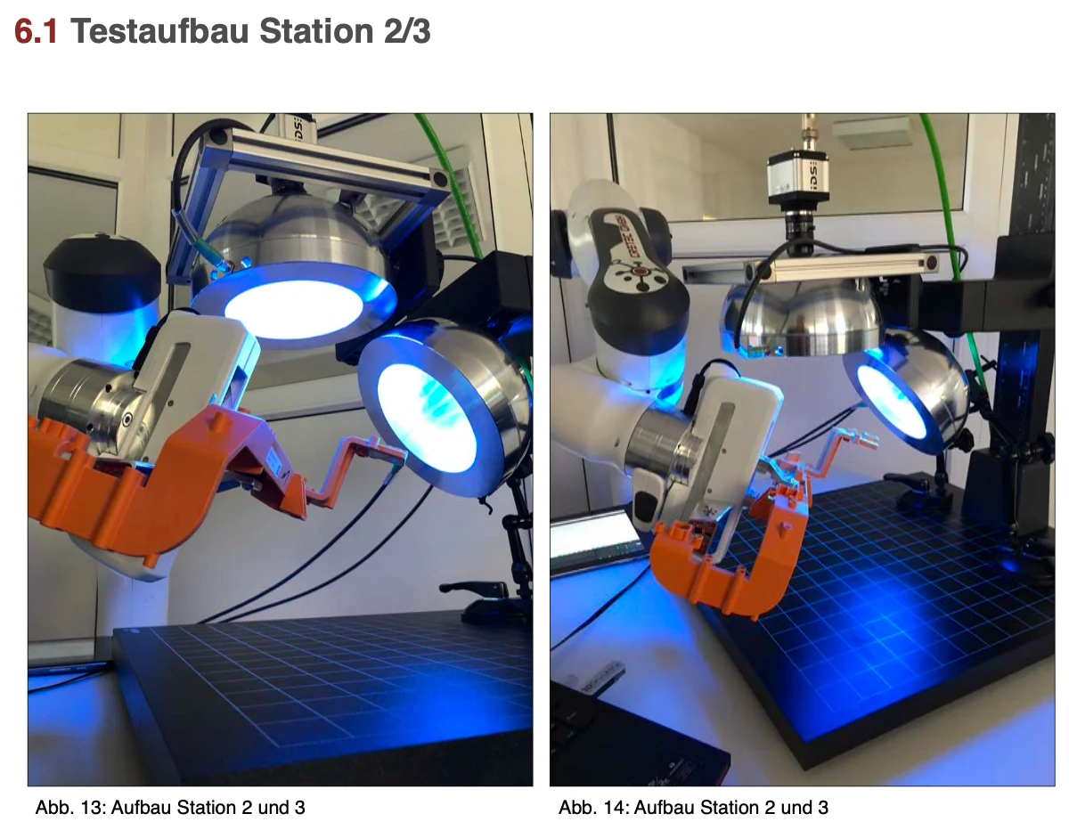
1.2 - Station 02 - Optical component control
Front face
The optical inspection of the components takes place variably.
A component may have 5 tests on the front or 12 tests. In principle, a fixed test sequence is defined for each component.
Exemplary test sequence at station 02:
1. Robot moves to component position 1 .
2. Robot Trigger 1 and Position 1 at BV System.
3. Optical control of the deposited test for item 1 example ‘Presence/position X,Y’.
4. SPS assumes the result of trigger 1, position 1.
5. Robot Trigger 1 and Position 2 at BV System.
6. Optical control of the deposited test for
Item 2 example: ‘Adhesive tape control’.
7. .....
8. PLC stores the result for the component.
9. Robot inserts component into mechanical/electrical testing.
Required tests at station 02:
- Presence and position X,Y (relatively in the picture) - Injected
- Excessive on contact surfaces
- Hole present (roughly)
- thread present (roughly)
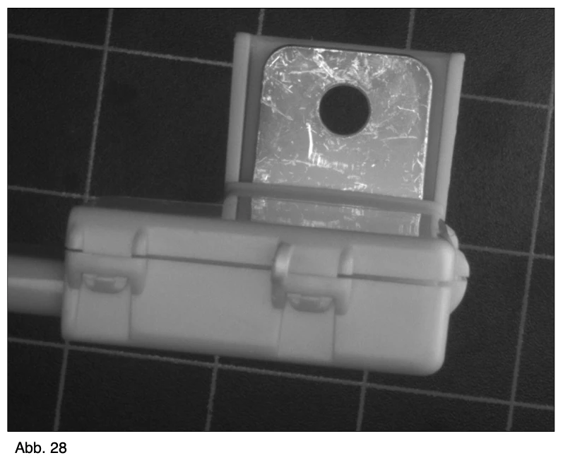
- Clip control of the latching lugs (roughly)
- adhesive tape control
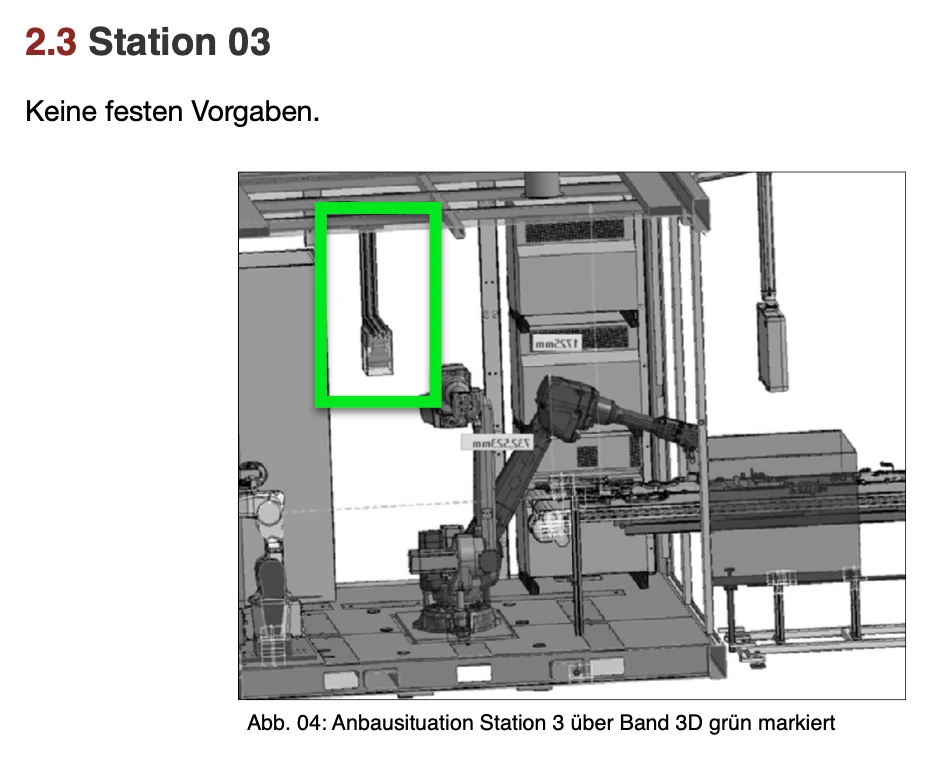
1.3 - Station 03 - Optical Component Control Backside
Procedure takes place as at station 02, only for the back.
Required tests at station 03: - Injected
- Excessive on contact surfaces
- Hole present (roughly)
- thread present (roughly)
- Clip control of the latching lugs (roughly) - adhesive tape control
1.4 - Station 04 (03) - Optical component control
Marking
Robot makes a grain point on the component (IO component) depending on the overall result. This grain point is checked at station 04. This takes place physically at station 03 . Furthermore, the grain point is also checked in the negative.
- In the case of NIO component, there must be no grain point on the grain site.
Required tests at station 04:
- Grain point present
Request for this application →